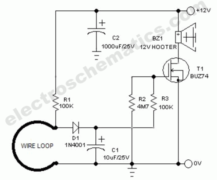
Understanding the Basics of Wiring Schematics and How it Relates to Circuits
When it comes to repairing, maintaining, or building electronic circuits, understanding wiring schematics is essential. This document contains all the necessary information about the components of a circuit and how each component works together to create a working system. From electricity flow, to physical components, and the components' interactions, wiring schematics have all the pertinent information for electrical engineers, technicians, and hobbyists alike. So what exactly does a wiring schematic tell us about a circuit? Let's dive in and explore.
What are Wiring Schematics and What Kinds of Information do They Provide?
Wiring schematics are circuit diagrams that provide detailed information on how electrical components are connected to one another. They show the exact path of current through the circuit, allowing technicians and engineers to understand the circuit’s overall functioning quickly. In addition to providing an overview of the paths taken by the electricity, wiring schematics also include the type of insulation used, along with the color codes for each wire. Understanding this information allows technicians to properly repair or replace components in the circuit.
How to Read a Wiring Schematic
Reading a wiring schematic requires a few fundamental principles of electronics. As already mentioned, wiring schematics indicate the type of insulation used on each wire, as well as their associated colors. Following the wires throughout the circuit will give you an idea of the circuit’s overall function. Additionally, the schematic labels each component in the circuit and the power source feeding each component. Being able to identify these components will help you diagnose electrical problems.
Common Components Found in Wiring Schematics
The most common components found in wiring schematics are: resistors, capacitors, and inductors. Each of these elements has its own purpose in the circuit and works with the other components to control the flow of electricity. Resistors are electrical components that reduce the amount of electricity flowing through the circuit. Capacitors store and release energy and help to maintain a steady flow of electricity. Inductors are coils that store energy and transform it from AC to DC electricity.
Other Components Found in Wiring Schematics
In addition to the common components previously discussed, wiring schematics also feature numerous other components that facilitate the flow of electricity. These components include transistors, diodes, LED drivers, and switches. Transistors are tiny devices that act like switches and help to control the flow of electricity. Diodes are two-terminal devices that control the flow of current in one direction. LED drivers are an important part of the circuit because they convert voltage to the level required by the LED components. Finally, switches allow engineers to turn on or off certain parts of the circuit.
Conclusion
In conclusion, wiring schematics are an invaluable resource for any engineer or technician. They provide extremely detailed information about a circuit and its components. Knowing how to read a wiring schematic correctly is essential when repairing, troubleshooting, or designing an electrical circuit. Understanding the common components found in wiring schematics, as well as the additional components that are necessary for controlling the flow of electricity, is also critical to success.

Circuits Lessons Blende

An Automatic Cw T R System For Vintage Stations Ac Wiring

Wiring Schematic Of The High Voltage Circuit Grounding Showing Scientific Diagram
What Is The Importance Of Using Schematic Diagrams In Representing Electric Circuits Quora

Wire Break Sensor Alarm Circuit Schematic

Single Line Diagram How To Represent The Electrical Installation Of A House Stacbond

How To Read The Electrical Diagram And What Are Symbols Involved In It Instrumentation Control Engineering

Wiring Design Electrical Circuit Schematics Solid Edge

The Control Circuit Wiring Diagram Scientific

Fig No 4 3 Circuit Diagram Of The Straightening And Cutting Machine Scientific

Difference Between Pictorial And Schematic Diagrams Lucidchart Blog

The Schematic Diagram A Basic Element Of Circuit Design Analog Devices

What Is The Meaning Of Schematic Diagram Sierra Circuits
Electrical Wiring Diagram Of The Four Point Measurement Setup Scientific

How To Read A Schematic Learn Sparkfun Com

Developing A Wiring Diagram Circuit 1

How To Read Car Wiring Diagrams Short Beginners Version Rustyautos Com

Schematic Symbols The Essential You Should Know

Your Home Electrical System Explained
