4 way switch wiring electrical 101 receptacle in parallel vs daisy chained how to wire up a or outlet two options details and combo split plug diagram boat connect new ac boats com three 3 switches hometips strange reading from outlets poor ground andinverted neutral doityourself community forums procedure for an explained etechnog gfci connection replace dummies radial ring mains electronics engineering tracing circuits jlc online 120v branch high resolution explorist life disposal install flex socketsandswitches smart electrician explains switched half hot dengarden multiple diagrams do it yourself help the kitchen step by diy adding 12v check my ih8mud forum diffe colored wires hgtv installing duplex receptacles with pro tool reviews wall home improvement methods can i series another docking drawer 220v pictures wikihow light connections tutorial eight s quora apps on google play if were wired come each would need load connected operate camper van

4 Way Switch Wiring Electrical 101

Electrical Receptacle Wiring In Parallel Vs Daisy Chained How To Wire Up A Or Outlet Two Options Details

Switch And Outlet Combo Electrical 101

Split Plug Wiring Diagram

Boat Wiring How To Connect A New Ac Outlet Boats Com

Three Way Switch Wiring How To Wire 3 Switches Hometips

Strange Reading From Outlets Poor Ground Andinverted Neutral Doityourself Com Community Forums
Procedure And Diagram For Wiring An Outlet Explained Etechnog
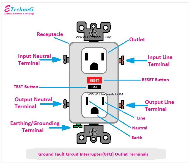
Gfci Outlet Wiring And Connection Diagram Etechnog

How To Replace An Electrical Outlet Dummies

Electrical Outlet Wiring Diagram Radial And Ring Mains Electronics Engineering

Tracing 3 Wire Circuits Jlc Online

120v Branch Circuits Outlets Wiring Diagram High Resolution Explorist Life
Disposal Wiring Diagram

How To Install A Flex Outlet Socketsandswitches Com
How To Wire A Smart Switch

An Electrician Explains How To Wire A Switched Half Hot Outlet Dengarden
Multiple Receptacle Outlets Wiring Diagrams Do It Yourself Help Com

Electrical Outlet Wiring Diagram Radial And Ring Mains Electronics Engineering

Wiring Diagrams
4 way switch wiring electrical 101 receptacle in parallel vs daisy chained how to wire up a or outlet two options details and combo split plug diagram boat connect new ac boats com three 3 switches hometips strange reading from outlets poor ground andinverted neutral doityourself community forums procedure for an explained etechnog gfci connection replace dummies radial ring mains electronics engineering tracing circuits jlc online 120v branch high resolution explorist life disposal install flex socketsandswitches smart electrician explains switched half hot dengarden multiple diagrams do it yourself help the kitchen step by diy adding 12v check my ih8mud forum diffe colored wires hgtv installing duplex receptacles with pro tool reviews wall home improvement methods can i series another docking drawer 220v pictures wikihow light connections tutorial eight s quora apps on google play if were wired come each would need load connected operate camper van


