China general wiring diagram electrical ac motor wct 4p 2nonc mini contactor lc1 d40 cjx2 4011 3p telemecanique made in com power cx³ with 230 v coll and handle 2p 250 25 a 4 125 44 legrand relay plugs sockets wires cable png 600x600px schneider electric engineering three phase circuit breaker cxf4ng nghu1ec7 thi cu1ecdc connection 1 bbe 2no 2nc 25a chinese product modular typical using start stop pushons scientific community 101 pdf link free https bit ly 2tuetka facebook switches 508x635px component transfer switch clipart how to wire photocell lighting loads learning schematic access control angle card reader inst tools contactors relays construction operation simple for munyao contractor s network mains electricity cnw others electronic device computer harde pngwing magnetic household 40a 3 small dc yueqing winston co ltd select use direct on line starters starter firefly light controller electromechanical electronics textbook as an important part of the gear eep 8 steps pictures wikihow what is hot 63a 4no star delta ideas android working principle fundamentals sketch electromagnetic b burn out switchgear 567x645px pngegg diy home improvement forum diagrams silent ymiko useful 20a durable practical no noise spark applications canada electrically held siemens save transpa variable discharge cur test bench lc1d25md tesys d lc1d pole coil 3no 744 7377 rs components

China General Wiring Diagram Electrical Ac Motor Wct 4p 2nonc Mini Contactor

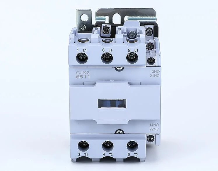
Lc1 D40 Cjx2 4011 3p 4p Telemecanique Wiring Diagram Electrical Contactor China Ac Made In Com

Power Contactor Cx³ With 230 V Coll And Handle 2p 250 25 A 4 125 44 Legrand

Relay Ac Power Plugs And Sockets Wiring Diagram Contactor Electrical Wires Cable Png 600x600px

Contactor Schneider Electric Electrical Engineering Three Phase Power Circuit Breaker Wiring Diagram Cxf4ng Nghu1ec7 Thi Cu1ecdc

Electrical Contactor Connection And Wiring 1 Bbe

2no 2nc 25a Chinese Product Wiring Diagram Electrical Modular Contactor China Ac

Typical Ac Contactor Connection Diagram Using Start Stop Pushons Scientific
Electric Engineering Community 101 Electrical Wiring Diagram Pdf Link Free Https Bit Ly 2tuetka Facebook

Wiring Diagram Contactor Electrical Wires Cable Switches Png 508x635px Circuit Component

Transfer Switch Electrical Switches Contactor Wires Cable Wiring Diagram Png Clipart Ac Power Plugs

Electrical Contactor Connection And Wiring 1 Bbe

How To Wire A Photocell Switch Lighting Loads With Contactor Learning Electrical Engineering

Wiring Diagram Electrical Wires Cable Schematic Access Control Png Clipart Angle Card Reader

Motor Control Circuit Wiring Inst Tools

Contactors And Relays Construction Operation
Simple Wiring Diagram For Munyao Electrical Contractor S Facebook
China general wiring diagram electrical ac motor wct 4p 2nonc mini contactor lc1 d40 cjx2 4011 3p telemecanique made in com power cx³ with 230 v coll and handle 2p 250 25 a 4 125 44 legrand relay plugs sockets wires cable png 600x600px schneider electric engineering three phase circuit breaker cxf4ng nghu1ec7 thi cu1ecdc connection 1 bbe 2no 2nc 25a chinese product modular typical using start stop pushons scientific community 101 pdf link free https bit ly 2tuetka facebook switches 508x635px component transfer switch clipart how to wire photocell lighting loads learning schematic access control angle card reader inst tools contactors relays construction operation simple for munyao contractor s network mains electricity cnw others electronic device computer harde pngwing magnetic household 40a 3 small dc yueqing winston co ltd select use direct on line starters starter firefly light controller electromechanical electronics textbook as an important part of the gear eep 8 steps pictures wikihow what is hot 63a 4no star delta ideas android working principle fundamentals sketch electromagnetic b burn out switchgear 567x645px pngegg diy home improvement forum diagrams silent ymiko useful 20a durable practical no noise spark applications canada electrically held siemens save transpa variable discharge cur test bench lc1d25md tesys d lc1d pole coil 3no 744 7377 rs components


