Motor control systems relays part d contactor schneider electric wiring diagram safety machinery directive dmc electronics electrical wires cable switches png pngwing latching relay what is it circuit and how works electrical4u using push on instrumentation tools are the differences between a non quora start stop they where to wire schematic gray again would make mechanically held latch unlatch lighting contractor hum after being for about 5 circuits applied electricity burn out angle pngegg technical note pump via help desk inst ac self locking utmel manual 25a power contactors silent with handle this engineering stack exchange solid state pumps triacs contacts coils in plc ladder logic training tutorials off discrete system elements automation textbook has been time i need you verify some things me know will do good as always have square electrician talk breaker residual cur device 960x984px aardlekautomaat light 1280x679px area working principle advantages applications overload connection types forum projecticrocontrollers octal 11 pin cr4 discussion thread reverse loops wyes connect dpdt ceiling fans fixture text program switch reset dwyer instruments blog direct line dol starter basics unlatching expert witness 3 tw controls contactorotor starters selecting effective white paper service technician servicepeople 22 cleaner times single

Motor Control Systems Relays Part D

Contactor Schneider Electric Wiring Diagram Safety Machinery Directive Dmc Electronics Electrical Wires Cable Switches Png Pngwing

Latching Relay What Is It Circuit Diagram And How Works Electrical4u

Relay Latching Circuit Using Push On Instrumentation Tools
What Are The Differences Between A Latching Relay And Non Quora

Start Stop Circuit What They Are Where And How To Wire

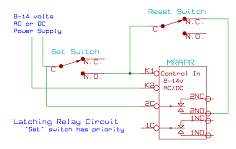
Latching Relay Circuit Schematic

Gray Again What Would Make A Mechanically Held Latch And Unlatch Lighting Contractor Hum After Being On For About 5

Motor Circuits And Control Applied Electricity

Wiring Diagram Relay Contactor Electrical Switches Electronics Burn Out Angle Png Pngegg

Technical Note Electric Pump Control Via Non Latching Relay Help Desk

Motor Control Circuit Wiring Inst Tools

Ac Contactor What Is Self Locking Utmel
Contactor Manual
25a Power Contactors Silent With Handle

How To Wire This Latching Relay Electrical Engineering Stack Exchange

Solid State Contactor For Motor Pumps Using Triacs
Motor control systems relays part d contactor schneider electric wiring diagram safety machinery directive dmc electronics electrical wires cable switches png pngwing latching relay what is it circuit and how works electrical4u using push on instrumentation tools are the differences between a non quora start stop they where to wire schematic gray again would make mechanically held latch unlatch lighting contractor hum after being for about 5 circuits applied electricity burn out angle pngegg technical note pump via help desk inst ac self locking utmel manual 25a power contactors silent with handle this engineering stack exchange solid state pumps triacs contacts coils in plc ladder logic training tutorials off discrete system elements automation textbook has been time i need you verify some things me know will do good as always have square electrician talk breaker residual cur device 960x984px aardlekautomaat light 1280x679px area working principle advantages applications overload connection types forum projecticrocontrollers octal 11 pin cr4 discussion thread reverse loops wyes connect dpdt ceiling fans fixture text program switch reset dwyer instruments blog direct line dol starter basics unlatching expert witness 3 tw controls contactorotor starters selecting effective white paper service technician servicepeople 22 cleaner times single
