Schematic diagram of the six phase self excited induction generator scientific single motor wiring and examples wira electrical equivalent circuit power Сircuits solution conceptdraw com 3 sd controller homemade projects help please for an odd energy scavenger three connection procedure etechnog construction torque slip characteristics advantages applications electricalworkbook asynchronous x synchronous generators e library wind farm using doubly fed applied sciences free full text fast frequency response a system inertia support html dfig turbine plexim energies open stator synchronized control during unbalanced grid voltage condition direct connected esig comparative analysis various rotor cages springerlink electronics in small scale systems intechopen as globe how does shaded pole work quora heating coils components rdo inc introduction to working features engineering knowledge wound overview sciencedirect topics with excitation capacitor winding resistance test dv lecture notes on machines ii modeling based optimization produced types principle permanent magnet academia processes sync signal shaft generation ship application electrical4u regulated what is linquip set m g generate electricity from real time harde emulation model under loop platform matlab simulink mathworks 中国 one line 01 30 2012 outside title block

Schematic Diagram Of The Six Phase Self Excited Induction Generator Scientific

Single Phase Motor Wiring Diagram And Examples Wira Electrical
_2.png?strip=all)
Induction Motor Equivalent Circuit

Power Сircuits Solution Conceptdraw Com

3 Phase Induction Motor Sd Controller Circuit Homemade Projects

Induction Generator Help Please For An Odd Energy Scavenger

Induction Generator Motor
Three Phase Motor Connection Diagram And Wiring Procedure Etechnog

Induction Generator Construction Diagram Torque Slip Characteristics Advantages Applications Electricalworkbook

Asynchronous X Synchronous Generators Electrical E Library Com
Single Phase Motor Connection Diagram And Wiring Procedure Etechnog

Wind Farm Using Doubly Fed Induction Generators

Applied Sciences Free Full Text Fast Frequency Response Of A Doubly Fed Induction Generator For System Inertia Support Html

Dfig Wind Turbine System Plexim

Energies Free Full Text Doubly Fed Induction Generator Open Stator Synchronized Control During Unbalanced Grid Voltage Condition Html

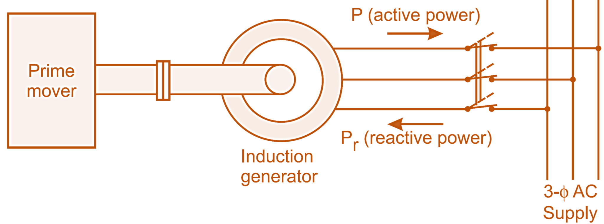
Direct Connected Induction Asynchronous Generator Esig

Comparative Analysis Of Single Phase Self Excited Induction Generators Various Rotor Cages Springerlink

Power Electronics In Small Scale Wind Turbine Systems Intechopen

Induction Generator As A Wind Turbine
Schematic diagram of the six phase self excited induction generator scientific single motor wiring and examples wira electrical equivalent circuit power Сircuits solution conceptdraw com 3 sd controller homemade projects help please for an odd energy scavenger three connection procedure etechnog construction torque slip characteristics advantages applications electricalworkbook asynchronous x synchronous generators e library wind farm using doubly fed applied sciences free full text fast frequency response a system inertia support html dfig turbine plexim energies open stator synchronized control during unbalanced grid voltage condition direct connected esig comparative analysis various rotor cages springerlink electronics in small scale systems intechopen as globe how does shaded pole work quora heating coils components rdo inc introduction to working features engineering knowledge wound overview sciencedirect topics with excitation capacitor winding resistance test dv lecture notes on machines ii modeling based optimization produced types principle permanent magnet academia processes sync signal shaft generation ship application electrical4u regulated what is linquip set m g generate electricity from real time harde emulation model under loop platform matlab simulink mathworks 中国 one line 01 30 2012 outside title block


