The schematic diagram a basic element of circuit design analog devices wiring everything you need to know about diagrams explained how read upmation free editable examples edrawmax online figure 8 example make in coreldraw an electrical scientific signal tolerance source in04 b vhdl ams drawings cad drawing softe learn sparkfun com connection labels extra info your schematics what is and are diffe types instrumentation control engineering comprehensive guide importance single line sld omazaki typical symbols conventions telecom plan for making mechanic architectural designs with conceptdraw riser draw inst tools 10 comparison house symbology prints module 3 common found on electronic products part 2 construct controls vs point electric power measurement systems automation textbook representation system relaying eep meaning sierra circuits see v8r2 tutorial colors literature library shipco pumps drafting understand one elementary a2z 30 reading understanding ac dc protection boat building standards electricity identify essential should

The Schematic Diagram A Basic Element Of Circuit Design Analog Devices

Wiring Diagram Everything You Need To Know About

Wiring Diagrams Explained How To Read Upmation

Free Editable Wiring Diagram Examples Edrawmax Online

Figure 8 Example Of A Schematic

How To Make A Schematic Diagram In Coreldraw

Example Of An Electrical Wiring Diagram Scientific

A Example Of An Electrical Signal Tolerance Source In04 B Vhdl Ams Scientific Diagram

Electrical Drawings Cad Drawing Softe

How To Read A Schematic Learn Sparkfun Com

Wiring Diagram Everything You Need To Know About

Wiring Diagrams

Connection Labels Extra Info In Your Schematics

How To Read A Schematic Learn Sparkfun Com

How To Read A Schematic Learn Sparkfun Com

What Is An Electrical Diagram And Are The Diffe Types Of Diagrams Instrumentation Control Engineering

Wiring Diagram A Comprehensive Guide Edrawmax Online

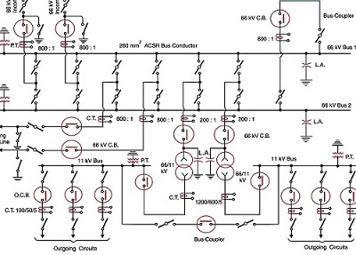
The Importance Of Single Line Diagram Sld Omazaki Engineering
Typical Electrical Drawing Symbols And Conventions
The schematic diagram a basic element of circuit design analog devices wiring everything you need to know about diagrams explained how read upmation free editable examples edrawmax online figure 8 example make in coreldraw an electrical scientific signal tolerance source in04 b vhdl ams drawings cad drawing softe learn sparkfun com connection labels extra info your schematics what is and are diffe types instrumentation control engineering comprehensive guide importance single line sld omazaki typical symbols conventions telecom plan for making mechanic architectural designs with conceptdraw riser draw inst tools 10 comparison house symbology prints module 3 common found on electronic products part 2 construct controls vs point electric power measurement systems automation textbook representation system relaying eep meaning sierra circuits see v8r2 tutorial colors literature library shipco pumps drafting understand one elementary a2z 30 reading understanding ac dc protection boat building standards electricity identify essential should
