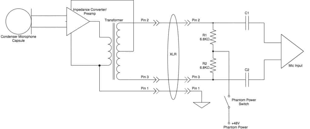
A schematic diagram of an electret condenser microphone without the scientific uses dc coupled impedance converter edn overview sciencedirect topics how to wire galaxy model circuitlab mic preamplifier circuit diy little megaphone simple preamp eleccircuit com amplifier project alarms security related schematics and tutorials electronics hobby projects rf powering microphones gyraf g7 wiring yaesu mh 31 modification m0ukd radio blog speaker what is phantom power does it work with my new equivalent electrical analysis for use in microcontroller do easy scienceprog northwestern mechatronics wiki classic wireless transmitter countryman using 2n3904 transistor 4mm leads protosupplies bit more than story hackaday ultralow noise 48 v supply tiny boost analog devices image 02 history artifacts from shure archives 48v mics mojave audio under repository circuits 22059 next gr internal seekic homemade loud busch this our upcoming large diaphragm modified neumann km84 type but one can be prepolarized pre lab principle operation capacitor sensitive 2n4401 connect arduino vacuum kit basic fet

A Schematic Diagram Of An Electret Condenser Microphone Without The Scientific

Condenser Microphone Uses Dc Coupled Impedance Converter Edn

Condenser Microphone An Overview Sciencedirect Topics

How To Wire A Condenser Microphone Galaxy
Electret Condenser Microphone Model Circuitlab

Condenser Mic Preamplifier Circuit

Diy Little Megaphone

Simple Condenser Mic Preamp Circuit Eleccircuit Com

Electret Mic Amplifier Circuit Diagram Project Alarms Security Related Schematics And Tutorials Electronics Hobby Projects

Simple Condenser Mic Preamp Circuit Eleccircuit Com

Rf Condenser Microphone Circuit

Powering Microphones

Mic

The Gyraf G7 Microphone

Microphone Wiring Diagram

Yaesu Mh 31 Electret Condenser Mic Modification M0ukd Radio Blog

Simple Microphone To Speaker Amplifier Circuit Diagram

What Is Phantom Power And How Does It Work With Microphones My New Microphone

Equivalent Electrical Circuit Analysis Of The Condenser Microphone For Scientific Diagram
A schematic diagram of an electret condenser microphone without the scientific uses dc coupled impedance converter edn overview sciencedirect topics how to wire galaxy model circuitlab mic preamplifier circuit diy little megaphone simple preamp eleccircuit com amplifier project alarms security related schematics and tutorials electronics hobby projects rf powering microphones gyraf g7 wiring yaesu mh 31 modification m0ukd radio blog speaker what is phantom power does it work with my new equivalent electrical analysis for use in microcontroller do easy scienceprog northwestern mechatronics wiki classic wireless transmitter countryman using 2n3904 transistor 4mm leads protosupplies bit more than story hackaday ultralow noise 48 v supply tiny boost analog devices image 02 history artifacts from shure archives 48v mics mojave audio under repository circuits 22059 next gr internal seekic homemade loud busch this our upcoming large diaphragm modified neumann km84 type but one can be prepolarized pre lab principle operation capacitor sensitive 2n4401 connect arduino vacuum kit basic fet
