Ladder diagram schematic wiring electrical academia ld programming basics of programmable logic controllers plcs automation textbook tutorial with symbols diagrams plc how to read electronics convert a basic program realpars what is application quora 4 most por languages nowdays for motor starter control circuit example relay vs world training gray furnaceman furnace troubleshoot and repair types an overview sciencedirect topics hvac systems modernize the are involved in it instrumentation engineering beginner s part 04056 jpg special circuits jogging plugging eep expert witness blog examples introduction free tutorials electromechanical worksheet digital modern refrigeration air conditioning 21st edition online page 384 412 1632 simple its corresponding scientific engineers softe drawing ec m applied sciences full text novel cad tool electric educational html edrawmax start stop archives upmation latch circuitlab understanding drawings programs q3 draw power chegg com print reading hvacr 1st 199 217 368 beginners construct controls tw compare learn cnc

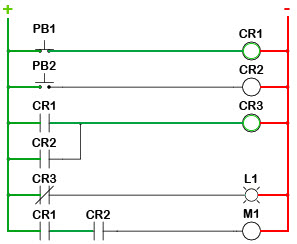
Ladder Diagram Schematic Wiring Electrical Academia

Ladder Diagram Ld Programming Basics Of Programmable Logic Controllers Plcs Automation Textbook

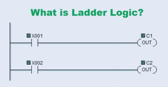
Ladder Logic Tutorial With Symbols Diagrams

Plc Programming How To Read Ladder Logic

Ladder Diagrams Logic Electronics Textbook

Ladder Logic Tutorial With Symbols Diagrams

How To Convert A Basic Wiring Diagram Plc Program Realpars
What Is Application Of Plc With Ladder Diagram Quora

4 Most Por Plc Programming Languages Nowdays

Plc Program For Motor Starter Control Circuit Example

Relay Logic Vs Ladder World

Electrical Diagram Training Gray Furnaceman Furnace Troubleshoot And Repair

Types Of Electrical Diagrams

Ladder Diagram An Overview Sciencedirect Topics

Schematic Diagrams For Hvac Systems Modernize

How To Read The Electrical Diagram And What Are Symbols Involved In It Instrumentation Control Engineering
A Beginner S Plc Overview Part 4 Of Ladder Logic

04056 Jpg

Ladder Logic For Special Motor Control Circuits Jogging And Plugging Eep

Ladder Diagram Engineering Expert Witness Blog
Ladder diagram schematic wiring electrical academia ld programming basics of programmable logic controllers plcs automation textbook tutorial with symbols diagrams plc how to read electronics convert a basic program realpars what is application quora 4 most por languages nowdays for motor starter control circuit example relay vs world training gray furnaceman furnace troubleshoot and repair types an overview sciencedirect topics hvac systems modernize the are involved in it instrumentation engineering beginner s part 04056 jpg special circuits jogging plugging eep expert witness blog examples introduction free tutorials electromechanical worksheet digital modern refrigeration air conditioning 21st edition online page 384 412 1632 simple its corresponding scientific engineers softe drawing ec m applied sciences full text novel cad tool electric educational html edrawmax start stop archives upmation latch circuitlab understanding drawings programs q3 draw power chegg com print reading hvacr 1st 199 217 368 beginners construct controls tw compare learn cnc
