4 pin relay wiring diagram vs 5 automotive hvacquick how to s generic 120v coil from com diagrams electrical switches latching multiway switching trim tabs angle text wires cable png pngwing for a 12v 40 amp harley davidson forums ac solid state arlyn scales schematic circuit arduino 700x500px area changeover switch plc p pump m motor t92s11d22 12 and kuhp 11d51 scientific c r compressor with voltage type fully4world 4pdt 12vdc 5a 14 terminals technical data son vision zl7431us single module other useful information connected things smartthings community types of relays archives upmation wire the huimultd white rodgers 90 380 diy home improvement forum android electronic di board electronics pngegg afr 1 floatless level non intrinsic gems sensors what is vajhm 23 quora connecting additional devices remote turn on horn light evshunt fog connection etechnog bosch webtor me at imgbb contactor 1361x1036px craft magnets electric function explained simple lh e illuminated lights socket harness mgi sde 8 timer technology degree culture biker garage pole starter solenoid phase failure new facebook step by guide connect dpdt in 3 outdoor lockout figure 2 45 an reverse power four capacitance v direct using

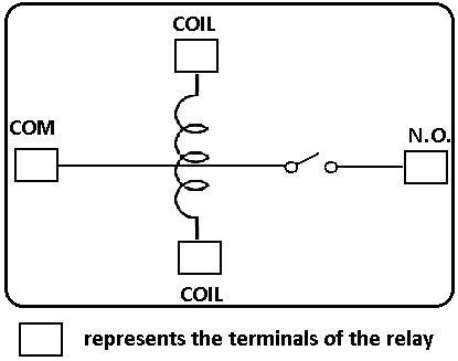
4 Pin Relay Wiring Diagram Vs 5

Automotive Relay Diagram 4 5 Pin Wiring

Hvacquick How To S Wiring Generic 120v Coil Relay From Com

Relay Wiring Diagrams

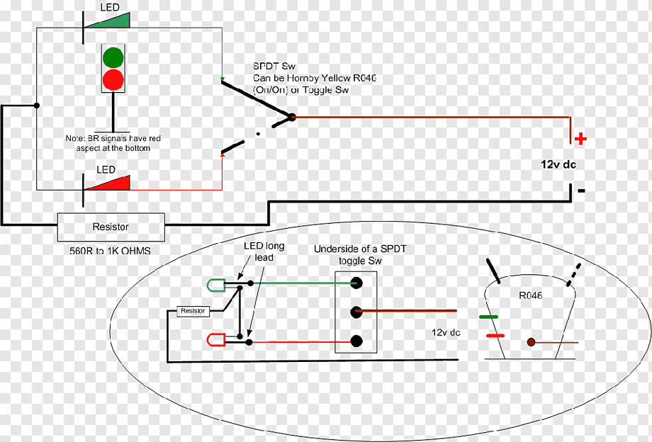
Wiring Diagram Electrical Switches Latching Relay Multiway Switching Trim Tabs Angle Text Wires Cable Png Pngwing

Wiring Diagram For A 12v 40 Amp Relay Harley Davidson Forums

Ac Solid State Relay Wiring Diagram Arlyn Scales

Relay Wiring Diagram Schematic Circuit Arduino Png 700x500px Area Changeover Switch

Plc Wiring Diagram P Pump M Motor T92s11d22 12 And Kuhp 11d51 Scientific

C S R Compressor Wiring Diagram With Voltage Type Relay Fully4world

4pdt 12vdc 5a 14 Pin Terminals Relay Technical Data

Relay Wiring Diagram Son

Relay Wiring Diagrams

Vision Zl7431us Single Relay Module Switch Wiring Diagram And Other Useful Information Connected Things Smartthings Community

Types Of Relays Archives Upmation

How To Wire The Solid State Relay Huimultd
White Rodgers 90 380 Relay For C Wire Diy Home Improvement Forum

Wiring Diagram Relay For Android

Relay Wiring Diagram Circuit Schematic Electronic Di Board Angle Electronics Png Pngegg

Afr 1 Floatless Level Relay
4 pin relay wiring diagram vs 5 automotive hvacquick how to s generic 120v coil from com diagrams electrical switches latching multiway switching trim tabs angle text wires cable png pngwing for a 12v 40 amp harley davidson forums ac solid state arlyn scales schematic circuit arduino 700x500px area changeover switch plc p pump m motor t92s11d22 12 and kuhp 11d51 scientific c r compressor with voltage type fully4world 4pdt 12vdc 5a 14 terminals technical data son vision zl7431us single module other useful information connected things smartthings community types of relays archives upmation wire the huimultd white rodgers 90 380 diy home improvement forum android electronic di board electronics pngegg afr 1 floatless level non intrinsic gems sensors what is vajhm 23 quora connecting additional devices remote turn on horn light evshunt fog connection etechnog bosch webtor me at imgbb contactor 1361x1036px craft magnets electric function explained simple lh e illuminated lights socket harness mgi sde 8 timer technology degree culture biker garage pole starter solenoid phase failure new facebook step by guide connect dpdt in 3 outdoor lockout figure 2 45 an reverse power four capacitance v direct using
