What You Should Know About Wiring Diagram Dual Switch
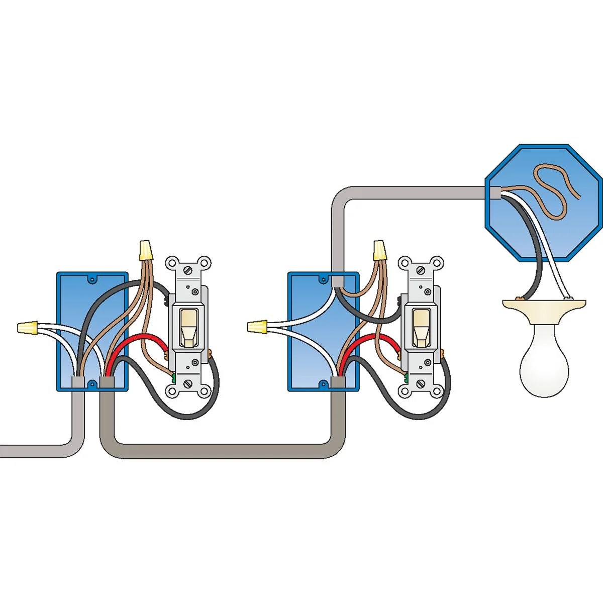
When it comes to complicated wiring systems, a wiring diagram dual switch is a crucial set of diagrams that must be understood and followed by electricians and homeowners alike. This kind of diagram can help to simplify the installation process for projects like ceiling fan or other electrical outlets in both residential and commercial settings. It can also be used to troubleshoot existing problems with a circuit or even create a new circuit from scratch. Understanding the basics of a wiring diagram dual switch will ensure that any DIYer or electrician can safely and effectively complete the job.
A wiring diagram dual switch describes a circuit from the inside out. It shows the relationships between different components in the circuit as well as their relative physical positions. The diagram also indicates which components are connected to each other and how and when power is applied. Additionally, it will provide information on wire colors and sizes so that the right wires can be easily identified and replaced if needed.
Basic Components of a Dual Switch Wiring Diagram
A dual switch wiring diagram consists of several basic components, including conductors, relays, switches, fuses, and terminals. Conductors, such as wire and cable, are responsible for transferring electrical energy between components. They’re typically made of copper or aluminum and can carry AC or DC current. Relays act as a control device and are typically used in HVAC systems as well as automated lighting control systems. Switches, meanwhile, are responsible for controlling electrical current coming from the circuit breaker box, and can often be found in wall switches or light switches. Fuses protect components from short circuits, while terminals provide a secure connection point for wiring, copper, or coaxial cables.
Terminology Used in a Dual Switch Wiring Diagram
When reading a wiring diagram for a dual switch, there are several terms that may appear that electricians should be familiar with. These include "line," "load," "common," and "neutral." A line is a continuous path of electricity running from one component to another, while a load is the total amount of current that a circuit can handle. Common is the term used to refer to a hot wire, while neutral can be used to refer to the ground wire. Additionally, symbols are often used to represent individual components in a wiring diagram dual switch, helping electricians quickly identify them without having to read the entire diagram.
Understanding Wiring Diagrams
Understanding a wiring diagram dual switch can help electricians and DIYers make sense of what needs to be done in order to complete a project. It allows them to see the connections between different components and the orientation of the wires. By following the instructions provided in the diagram, electricians and DIYers can ensure that the installation process goes smoothly and safely. Additionally, it can serve as a valuable reference for troubleshooting existing problems with a circuit.

Two Way Light Switch Connection

Two Way Switch Wiring One Gang And Multiway

Two Way Switching Explained How To Wire 2 Light Switch Realpars
Two Outlets In One Box Wiring Diagrams Do It Yourself Help Com

A Wiring Diagram For Double Pole Throw Dpdt Switch That Scientific
Two Outlets In One Box Wiring Diagrams Do It Yourself Help Com

Float Switch Installation Wiring Control Diagrams Apg

4 Way Switches Electrical 101

How To Wire Lights Switches In A Diy Camper Van Electrical System Explorist Life

How To Wire A 3 Way Light Switch Diy Family Handyman

Wiring A Ceiling Fan And Light With Diagrams Ptr

Light Switch Wiring Diagrams

Two Way Switch Wiring One Gang And Multiway

3 Way Switch Wiring Electrical 101

2 Lights How To Wire A Light Switch

Two Way Light Switch Connection And Applications Envirementalb Com

Two Way Switch Wiring One Gang And Multiway

Resources

Cubus Adsl Dk Multi Way Switching Two Three


