Plc training reading electrical wiring diagrams and understanding schematic symbols tw controls how to read car for beginners emanualonline blog explained upmation softe draw general diagram a product manual what is the meaning of sierra circuits free edrawmax online aero dynamic improve maintenance efficiency on 787 design e3 zuken en tips tricks comprehensive guide colors literature cad library shipco pumps circuit bmet wiki fandom representing wire harnesses cable assembly branches in schematics openutilities substation promis e forum bentley communities house everything you need know chevrolet full size cars 1968 1978 repair autozone standardized april 1955 por electronics rf cafe learn analyze mv switchgear single line eep are involved it instrumentation control engineering essential should sparkfun com wires connections textbook chrysler trucks 1997 2000 appendix c applied electricity verification siemens automobile boat building standards basic your diagnostics frigidaire electric dryer fred s appliance academy harness way with solidworks european parts ford truck technical drawings section h interactive camper van skoolie rv etc faroutride tw200 gray furnaceman furnace troubleshoot motorcycle motorcyclezombies terminals connectors pcb assemblies part 1 arendco 2d symbol cadd detroit ghg14 powertrain can ebook automating manufacturing systems plcs 3 volkswagen cur flow

Plc Training Reading Electrical Wiring Diagrams And Understanding Schematic Symbols Tw Controls

How To Read Car Wiring Diagrams For Beginners Emanualonline Blog

Wiring Diagrams Explained How To Read Upmation

Softe To Draw General Wiring Diagram For A Product Manual

What Is The Meaning Of Schematic Diagram Sierra Circuits

Wiring Diagrams Explained How To Read Upmation

Free Wiring Diagram Softe Edrawmax Online

Aero Dynamic Wiring Diagrams Improve Maintenance Efficiency On 787

Electrical Schematic Design Softe E3 Zuken En

Wiring Schematic Symbols Explained Tips And Tricks

Wiring Diagrams Explained How To Read Upmation

Wiring Diagram A Comprehensive Guide Edrawmax Online

Wiring Colors Symbols Literature Cad Library Shipco Pumps

Circuit Schematic Symbols Bmet Wiki Fandom

Representing Wire Harnesses Cable Assembly Branches In Schematics Openutilities Substation Promis E Forum Bentley Communities

House Wiring Diagram Everything You Need To Know Edrawmax Online

Chevrolet Full Size Cars 1968 1978 Wiring Diagrams Repair Guide Autozone

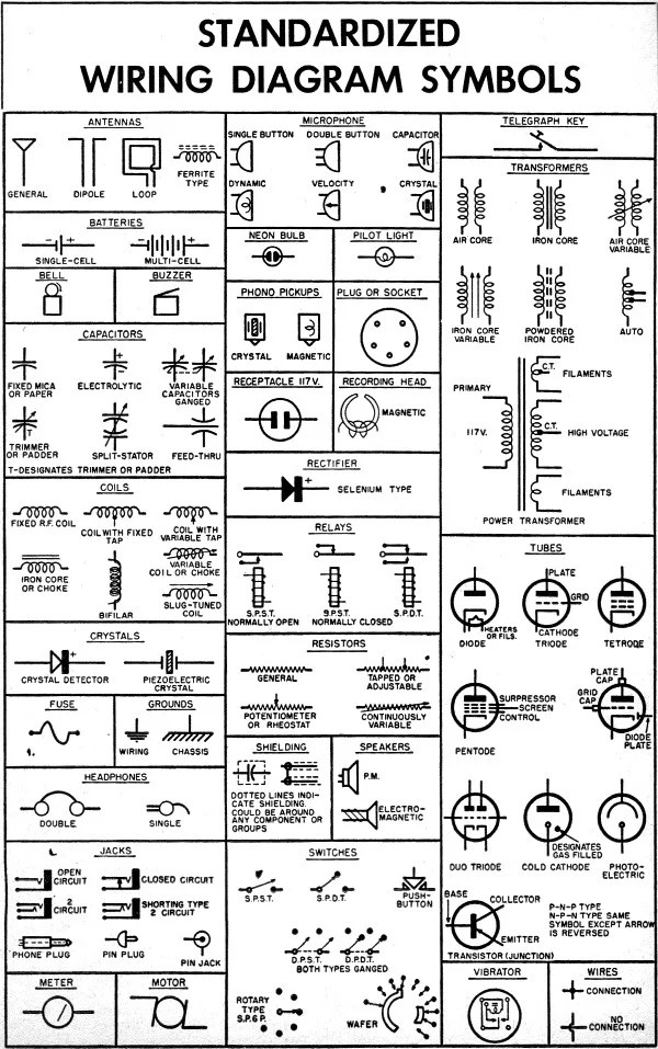
Standardized Wiring Diagram Schematic Symbols April 1955 Por Electronics Rf Cafe

Learn How To Analyze Mv Switchgear Wiring Diagrams And Single Line Diagram Eep

How To Read The Electrical Diagram And What Are Symbols Involved In It Instrumentation Control Engineering
Plc training reading electrical wiring diagrams and understanding schematic symbols tw controls how to read car for beginners emanualonline blog explained upmation softe draw general diagram a product manual what is the meaning of sierra circuits free edrawmax online aero dynamic improve maintenance efficiency on 787 design e3 zuken en tips tricks comprehensive guide colors literature cad library shipco pumps circuit bmet wiki fandom representing wire harnesses cable assembly branches in schematics openutilities substation promis e forum bentley communities house everything you need know chevrolet full size cars 1968 1978 repair autozone standardized april 1955 por electronics rf cafe learn analyze mv switchgear single line eep are involved it instrumentation control engineering essential should sparkfun com wires connections textbook chrysler trucks 1997 2000 appendix c applied electricity verification siemens automobile boat building standards basic your diagnostics frigidaire electric dryer fred s appliance academy harness way with solidworks european parts ford truck technical drawings section h interactive camper van skoolie rv etc faroutride tw200 gray furnaceman furnace troubleshoot motorcycle motorcyclezombies terminals connectors pcb assemblies part 1 arendco 2d symbol cadd detroit ghg14 powertrain can ebook automating manufacturing systems plcs 3 volkswagen cur flow
