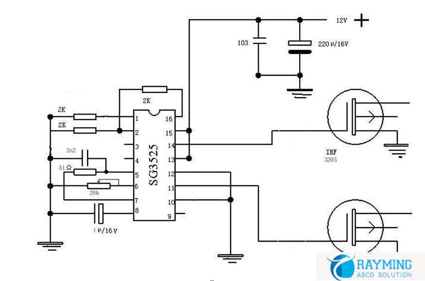
Constructing an Inverter Circuit Using the TL494 IC
With modern advances in technology, it is sometimes necessary to construct an inverter circuit to convert AC power to DC power and vice versa. When making this conversion, engineers use the TL494 Integrated Circuit (IC) to control the switching of the circuit and maintain the voltage levels at a constant level. The TL494 IC is also used to regulate voltage when multiple supplies are being used, such as in a motor drive application. In this article we will explain how to construct an inverter circuit using the TL494 IC.
Design Considerations for Constructing an Inverter Circuit using the TL494 IC
When designing an inverter circuit using the TL494 IC, one must consider the type of output required, and the type of control signal needed. The output voltage can be either a sinusoidal or a modified sinusoidal waveform depending on the application. The modified sinusoidal waveform is more suitable for applications such as motor drives, as it has a higher frequency than the sinusoidal waveform.
In order to achieve a well-controlled output, it is important to have the correct control signal applied to the TL494 IC. This control signal can be a current source, a digital signal, or a pulse width modulation (PWM) signal. A current source is the most commonly used control signal and it must be scaled properly in order for the output voltage to remain at a constant level. Digital signals, however, require the use of a counter and comparator circuit, while PWM signals are used for more sophisticated designs.
Components Used in the Inverter Circuit
The components used in the inverter circuit vary from design to design, but typically include the following:
- TL494 IC
- Voltage regulator
- Transformer
- Bridge rectifier
- Capacitor
- Inductor
- Switch
- Fuse
The voltage regulator is used to ensure that the output voltage remains consistent regardless of load or temperature variations. The transformer is responsible for transforming the incoming AC power into a suitable form for the inverter circuit. The bridge rectifier converts the AC voltage into DC voltage for the circuit, while the capacitor and inductor are used to filter the output. The switch determines when the output is turned on or off, while the fuse provides protection against overloads or short circuits.
Features of the TL494 IC
The TL494 IC offers several features that make it ideal for constructing inverter circuits. It has a built-in oscillator which can be used to generate the control signal for controlling the switching of the circuit. The IC also provides protection against overvoltage and undervoltage conditions, as well as thermal shutdown protection. Additionally, the TL494 IC is available in various packages, making it suitable for both through-hole and surface mount applications.
Overall, the TL494 IC is a versatile component for constructing inverter circuits. With its wide range of features and protection, the TL494 IC is an ideal choice for any application requiring AC-to-DC power conversion. By understanding the design considerations and components used, engineers can easily construct an inverter circuit using the TL494.
Tl494 Pulse Width Modulation Control Circuits Datasheet Rev H

How To Make A Simple 100w High Frequency Inverter Printed Circuit Board Manufacturing Pcb Assembly Rayming

Cd4047be Inverter Circuit 12v To 220v 100 Watts Soldering Mind

Buck Solar Charger Circuit Using Ic Tl494

Relationship Between Duty And Control Voltage Of The Tl494 Pwm Scientific Diagram

Pwm Inverter Circuit Diagram Using Tl494

Tl494 Pwm Module Fixed Frequency Driver Board For Dc Converter Inverter Motronix

Introduction To Tl494 The Engineering Projects

12v 24v Pwm Motor Controller Circuit Using Tl494 Irf1405

Solved Dc To Ac Inverter H Bridge Forum For Electronics

Tl494 Pwm Ic Pinout Examples Features Datasheet And Applications

Pwm Inverter Circuit Using Tl494

Inverter Circuit Page 5 Power Supply Circuits Next Gr

Pwm Inverter Circuit Diagram Using Tl494

Inverter 12v To 220v Using Tl494 Share Project Pcbway

Inverter Circuit Page 2 Power Supply Circuits Next Gr

Pwm Inverter Circuit Diagram Using Tl494

Project Lab Inverter 33 Basic4mcu Com

Dc To Converter Circuit Tl494 12v 30v Adjule Electronics Projects Circuits

A Common Car Inverter Circuit And Principle Under Demodulators Circuits 59809 Next Gr
