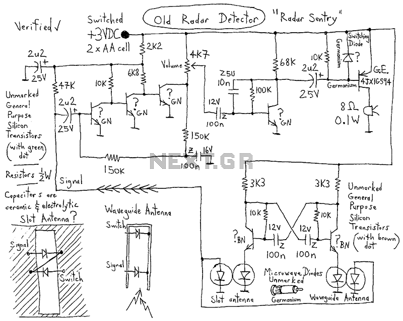
Understanding Simple Radar Circuit Diagrams: How They Help Improve Financial Tracking
Radar circuits are ubiquitous in technology today, with applications ranging from consumer electronics to consumer finance. From consumer electronics like watches, medical scanners or even cell phones, to consumer financial tracking, these circuits have revolutionized the way we interact with money and the world at large. Radar circuits provide an invaluable tool for individuals and organizations to track their financial health. In this article, we will explore the basics of simple radar circuit diagrams and how they can be used to better understand and track financial data.
What Is a Simple Radar Circuit Diagram?
A simple radar circuit diagram is a basic graphical representation of a radar system, which is a type of electronic detection system. Radar systems detect movement or change in environment by emitting electromagnetic waves and then analyzing the reflections of these waves. They are commonly used in security and military technology, navigation systems and more recently in consumer electronics. The simple radar circuit diagram provides a basic representation of the components and connections within a radar system, allowing users to better understand the functionality and internals of the system.
Applications of Simple Radar Circuit Diagrams in Finance
Simple radar circuit diagrams can be used to improve financial tracking by providing users with an essential tool for understanding and analyzing financial information. For example, these diagrams can be used to identify potential business opportunities, or to assess the financial risk associated with certain investments. By providing a graphical representation of the components and logic of a radar system, users can quickly and accurately track the performance of specific investments and make informed decisions about their finances.
Benefits of Using Radar Circuit Diagrams for Financial Tracking
Using a simple radar circuit diagram for financial tracking provides a number of benefits. Firstly, it helps users identify opportunities, risks and patterns in their financial activities. By visually mapping out the components, users are able to quickly analyze current trends and make strategic decisions based on the insights offered by the diagram. This, in turn, can help users save time and money while improving the accuracy of their financial tracking.
Furthermore, radar circuit diagrams enable users to track their financial activities in real-time. By continuously monitoring their finances via the circuit diagram, users are able to identify and respond to events and changes in their financial situation quickly and accurately. This can be especially useful for users with complicated financial situations such as investment portfolios, where changes in the market can have drastic and immediate consequences.
Finally, radar circuit diagrams offer users a comprehensive view of their financial situation, providing a comprehensive overview of their long-term financial health. This allows users to assess their overall outlook and make the best decisions for their future.
Conclusion: Why Simple Radar Circuit Diagrams Are Essential for Financial Tracking
Simple radar circuit diagrams are essential for efficient and accurate financial tracking. The diagrams provide users with a comprehensive and visual representation of the walls of their financial situation, allowing them to identify opportunities, risks and trends in their financial activities. This, in turn, enables users to save time, money and effort while making informed decisions. Finally, radar circuit diagrams enable users to monitor their financial situation in real-time, ensuring that they are always aware of any changes or developments in their financial state.

Results Page 304 About Counter Up And Down Searching Circuits At Next Gr
Third Version Of Homemade 6 Ghz Fmcw Radar Henrik S Blog

Simple Radar Project Tinkercad

Block Diagram Of The 2 4 Ghz Doppler Radar Integrated On Printed Scientific

What Is Radar System Definition Basic Principle Block Diagram And Applications Of Electronics Desk

Block Diagram Of Fmcw Radar System With Overview Photograph The Scientific

Ultrasonic Radar Circuit Diagrams Schematics Electronic Projects

Arduino Radar Project Using Ultrasonic Techatronic

Radar Concepts Ece 480 Team 5 Interactive Demonstration

Hb100 Microwave Radar To Arduino

Arduino Radar Model With Ultrasonic Sensor Servo Lcd

How To Build Economy Radar Detector Circuit Diagram

General Block Diagram Of The Radar System Scientific

Block Diagram Of The Heterodyne Fmcw Radar Sensor With A Six Port Scientific

Radar Basics Types Working Range Equation Its Applications

Ultrasonic Radar Circuit Diagrams Schematics Electronic Projects

Radar Detector Under Rf Radiation Circuits 14337 Next Gr
Radar Silicon Wiki

Simple Light Sensor Circuit

