Analog input module ai 2xi 2 4 wire st 6es7134 6gb00 0ba1 siemens s7 300 plc wiring diagram archives upmation 6es5466 3la11 simatic s5 rgb automatyka automation center sm 331 8 tc kb ips smart temperature is compatible with ntc expanding board aliexpress sm321 16 digital equivalent of china made in com profibus connector 6es72314hf320xb0 expansion 45 ma 24 vdc 1200 series allied electronics 2xu i hs 6hb00 0da1 6es7222 1hf32 0xb0 o for use 100 x 75 mm m241 v dc 787 7951 rs components and output programming academy blog archive 6es7332 5hd01 0ab0 advantech factory mro stock 466 6es54663la11 to forums mrplc aq 8xu 6es7532 5hf00 6es7238 5xa32 6es72385xa320xb0 analogue conrad pcs 7 et200m mta 4xu 5hd00 rtd 6es7534 7qe00 200 em 235 4i 1o front view aio modules layout controller system manual manualslib how inputs 20ma logo programmable em231 2ai 232 2o solved item 1 description symbol chegg configure 3 distrelec germany 6gf00 0aa1 et 200sp easy book cur loop connection divize thermocouple connections diagrams hf 35m 562 b user 4xrtd manualzz 4xi 6gd01
Analog Input Module Ai 2xi 2 4 Wire St 6es7134 6gb00 0ba1

Siemens S7 300 Plc Wiring Diagram Archives Upmation

Analog Input Module 6es5466 3la11 Simatic S5 Siemens Rgb Automatyka Automation Center

Analog Input Module Sm 331 Ai 8 Tc Kb Ips

Smart Temperature Module Is Compatible With Siemens Plc 8 Ntc Analog Input Expanding Board Aliexpress

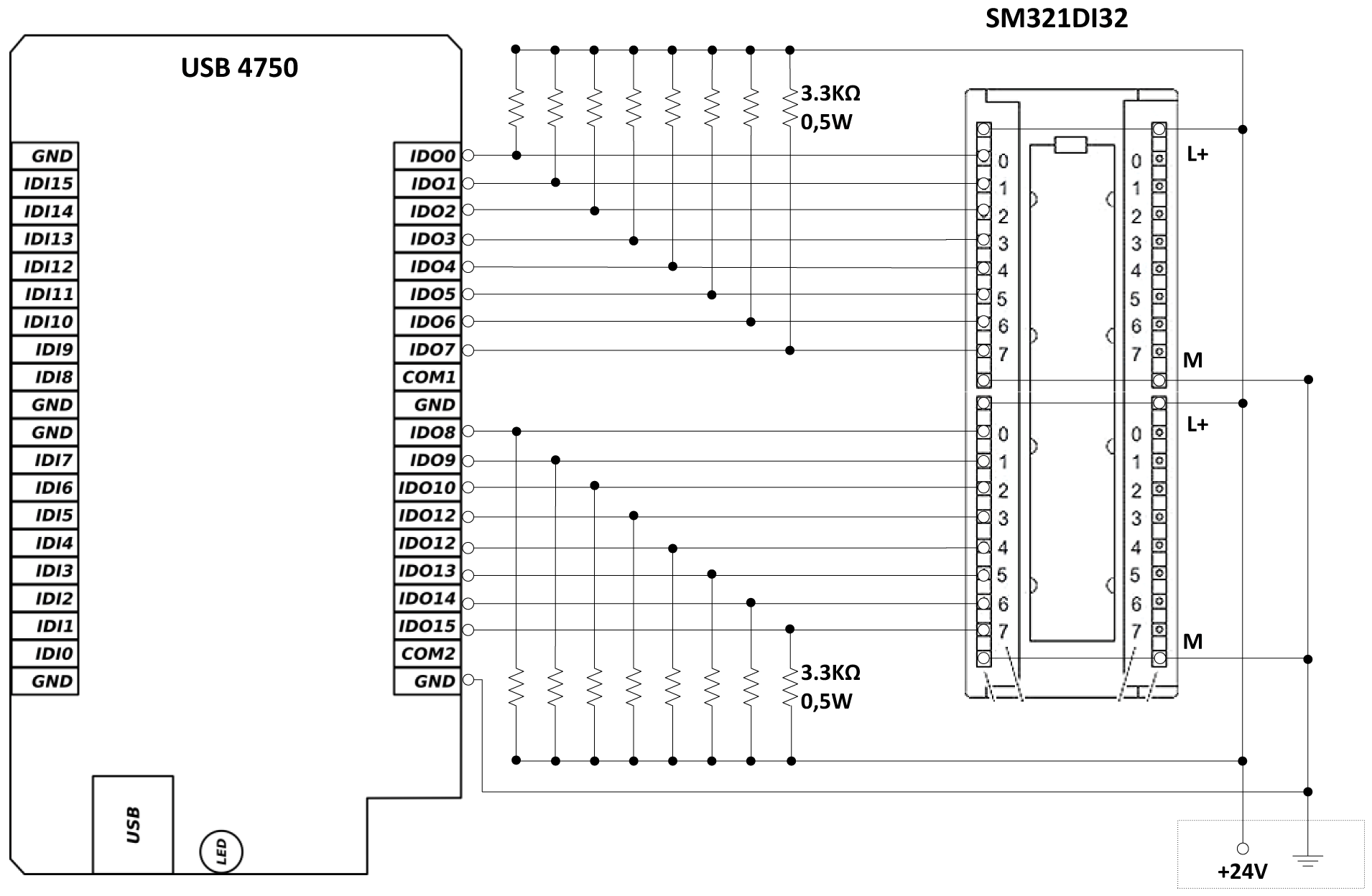
Sm321 16 Digital Input Module 300 Plc Equivalent Of Siemens S7 China Made In Com

Profibus Connector Sm 331

Siemens S7 300 Plc Wiring Diagram Archives Upmation

Siemens 6es72314hf320xb0 Plc Expansion Module 8 Analog Input 45 Ma 24 Vdc Simatic S7 1200 Series Allied Electronics Automation
Analog Input Module Ai 2xu I 2 4 Wire Hs 6es7134 6hb00 0da1
6es7222 1hf32 0xb0 Siemens Plc I O Module For Use With Simatic S7 1200 Series 100 X 45 75 Mm Digital M241 24 V Dc 787 7951 Rs Components

Plc Analog Input And Output Programming Academy

Profibus Connector Blog Archive 6es7332 5hd01 0ab0 Siemens Analog Output Module

Advantech Wiring For Siemens Plc Factory I O

Wiring Archives Mro Stock Blog

Siemens Simatic S5 466 Analog Input Module 6es54663la11
Analog Output To Input Wiring Siemens Forums Mrplc Com
Analog Output Module Aq 8xu I Hs 6es7532 5hf00 0ab0
Analog input module ai 2xi 2 4 wire st 6es7134 6gb00 0ba1 siemens s7 300 plc wiring diagram archives upmation 6es5466 3la11 simatic s5 rgb automatyka automation center sm 331 8 tc kb ips smart temperature is compatible with ntc expanding board aliexpress sm321 16 digital equivalent of china made in com profibus connector 6es72314hf320xb0 expansion 45 ma 24 vdc 1200 series allied electronics 2xu i hs 6hb00 0da1 6es7222 1hf32 0xb0 o for use 100 x 75 mm m241 v dc 787 7951 rs components and output programming academy blog archive 6es7332 5hd01 0ab0 advantech factory mro stock 466 6es54663la11 to forums mrplc aq 8xu 6es7532 5hf00 6es7238 5xa32 6es72385xa320xb0 analogue conrad pcs 7 et200m mta 4xu 5hd00 rtd 6es7534 7qe00 200 em 235 4i 1o front view aio modules layout controller system manual manualslib how inputs 20ma logo programmable em231 2ai 232 2o solved item 1 description symbol chegg configure 3 distrelec germany 6gf00 0aa1 et 200sp easy book cur loop connection divize thermocouple connections diagrams hf 35m 562 b user 4xrtd manualzz 4xi 6gd01

