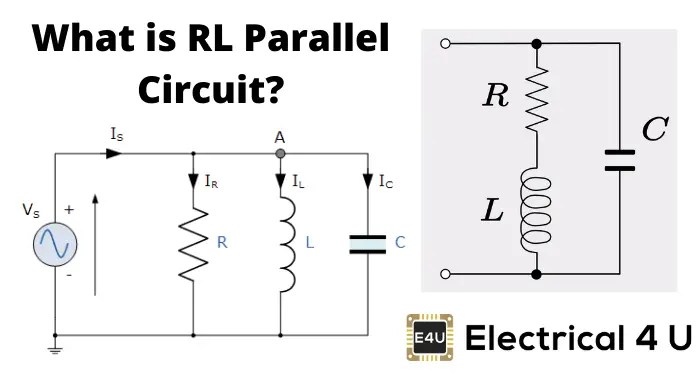
Schematic Wiring Diagram Of Series And Parallel Circuit

By | January 19, 2022


Understanding the Schematic Wiring Diagram of Series and Parallel Circuits


Schematic wiring diagrams, also referred to as electrical circuit diagrams, are an essential tool for any electrician, engineer, or technician working in the field of electronics. They play an important role in helping technicians identify the proper connections between components and understand how electricity is being distributed throughout the system. In particular, a schematic wiring diagram of series and parallel circuits can provide a wealth of information about the interactions between different electrical paths.


Electrical circuits can be divided into two main categories: series circuits and parallel circuits. In a series circuit, the current follows the same path through all of the components of the circuit, whereas in a parallel circuit, the current can flow independently through multiple components. It is important to note that series and parallel circuits have different characteristics, which is why understanding the distinctions between them is key to correctly wiring a system. The following sections describe the differences between series and parallel circuits, as well as how to create a schematic wiring diagram for each type.


The Basics of Series and Parallel Circuits


Series circuits consist of components connected in one single loop, while in a parallel circuit, components are connected in multiple loops. In a series circuit, the current will follow the same path through all of the components, and if one component fails, the current will not be able to pass through the circuit. On the other hand, a parallel circuit has multiple paths for the current to take, and if one component fails, the current can still pass through the other components.


When designing a series circuit, it is important to remember that the resistance of each component will add up. For example, if you have two resistors with a resistance of 2 ohms each, then the total resistance of the circuit will be 4 ohms. On the other hand, in a parallel circuit, the resistance of each component will not add up. This means that if you have two resistors with a resistance of 2 ohms each, the total resistance of the circuit will still be 2 ohms. This can be useful in certain applications, as it allows you to use fewer components in order to achieve a certain level of resistance.


Designing a Schematic Wiring Diagram Of Series And Parallel Circuit


A schematic wiring diagram is a drawing that shows the electrical connections between the components in a circuit. It is important to note that when creating a schematic diagram of a series circuit, all components should be connected in one single loop. On the other hand, in a parallel circuit, components are connected in multiple loops. When designing a schematic wiring diagram of a series circuit, it is important to remember that the current will follow the same path through all of the components. As such, you should be aware of the individual resistance of each component, as this will determine the total resistance of the circuit.


When creating a schematic wiring diagram of a parallel circuit, it is important to remember that the current can follow multiple paths in order to reach the desired endpoint. As such, there will be multiple components that are connected in multiple loops, rather than one single loop. Additionally, you should be aware of the resistance of each component, as this will determine the overall resistance of the circuit. In some cases, a parallel circuit may consist of components that are working in tandem in order to achieve a certain level of resistance.


Conclusion


In conclusion, schematic wiring diagrams of series and parallel circuits are a key tool for any electrician, engineer, or technician. It is important to remember that a series circuit consists of components that are connected in one single loop, while in a parallel circuit, components are connected in multiple loops. When creating a schematic wiring diagram of a circuit, it is important to keep in mind the individual resistance of each component, as this will determine the total resistance of the circuit. By understanding the differences between series and parallel circuits, you will be able to more effectively design and construct a system.


Vol I Direct Cur Dc Series Parallel Combination Circuits Re Drawing Complex Schematics

Vol I Direct Cur Dc Series Parallel Combination Circuits Re Drawing Complex Schematics


Building Simple Resistor Circuits Series And Parallel Electronics Textbook

Building Simple Resistor Circuits Series And Parallel Electronics Textbook


Series Parallel Circuit Examples Electrical Academia

Series Parallel Circuit Examples Electrical Academia


What Are Series And Parallel Circuits Electronics Textbook

What Are Series And Parallel Circuits Electronics Textbook


Series And Parallel Circuits Learn Sparkfun Com

Series And Parallel Circuits Learn Sparkfun Com


Parallel Circuits

Parallel Circuits


Led Circuits

Led Circuits


Multiple Receptacle Outlets Wiring Diagrams Do It Yourself Help Com

Multiple Receptacle Outlets Wiring Diagrams Do It Yourself Help Com


Difference Between Series And Parallel Circuit With Comparison Chart Globe

Difference Between Series And Parallel Circuit With Comparison Chart Globe


Schematics Wiring Solar Panels And Batteries In Series Parallel

Schematics Wiring Solar Panels And Batteries In Series Parallel


Difference Between Series And Parallel Circuit With Comparison Chart Globe

Difference Between Series And Parallel Circuit With Comparison Chart Globe


Parallel Circuit Images Browse 4 281 Stock Photos Vectors And Adobe

Parallel Circuit Images Browse 4 281 Stock Photos Vectors And Adobe


Circuit Analysis

Circuit Analysis


Series Parallel Circuit Examples Electrical Academia

Series Parallel Circuit Examples Electrical Academia


Difference Between Series And Parallel Circuits With Its Practical Applications In Real Life

Difference Between Series And Parallel Circuits With Its Practical Applications In Real Life


Multiple Receptacle Outlets Wiring Diagrams Do It Yourself Help Com

Multiple Receptacle Outlets Wiring Diagrams Do It Yourself Help Com


Parallel Circuit Images Browse 4 281 Stock Photos Vectors And Adobe

Parallel Circuit Images Browse 4 281 Stock Photos Vectors And Adobe