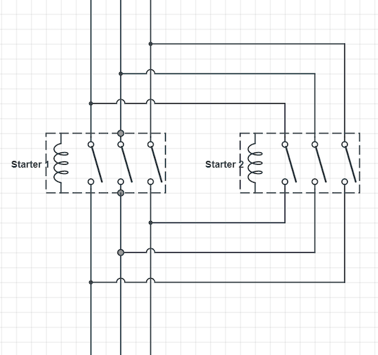
Understanding the Complexities of Three-Phase Motor Connection Diagrams
Understanding the complexities of a three-phase motor connection diagram can be a valuable asset for anyone working in maintenance, installation, and repair of electric motors. It is especially important for those in the industry who are familiar with AC electrical systems, as three-phase motors are commonly used in AC applications. While the diagram may appear complicated to an untrained eye, a closer look reveals that understanding the diagram is not nearly as difficult as it initially appears. By learning the basics of three-phase motor connection diagrams, one can quickly and effectively identify the circuit components and determine the best connection points for their application.
The three-phase motor connection diagram's layout incorporates a variety of symbols to accurately represent the circuit components, such as transformers, switches, and wires. Each of these symbols is designed to provide visual information as well as indicator direction, allowing the user to understand the motor’s operation. This article will guide you through a three-phase motor connection diagram and explain each of the symbols used, providing a helpful resource for anyone working with electric motors.
What is a Three-Phase Motor?
A three-phase motor is an alternating current (AC) motor that utilizes a three-phase power source. These types of motors are commonly used in industries such as agriculture, factories, and manufacturing, where a lot of electricity is needed in order to operate. They are also perfect for variable speed applications, as the voltage can be adjusted through the use of variable frequency drives. This makes them ideal for pumps and conveyors that need to be able to change their speed at a moment's notice.
The three-phase power source provides voltage to the motor in the form of three sinusoids, or alternating waves. These sine waves are phased 120° apart, meaning that each one reaches its peak one third of a cycle after the previous one. The benefit of this type of motor is that it is more efficient than single phase motors, as they can take advantage of the sum of the individual sine waves.
Main Components of a Three-Phase Motor Connection Diagram
The main components of a three-phase motor connection diagram are the power source, controller, motor, and various switches. The power source is typically an external AC source that supplies the motor with three-phase power. The controller is a device that regulates the flow of power from the power source to the motor. This is usually done through the use of adjustable relays or variable frequency drives that allow the user to make adjustments based on their specific needs. Finally, the switches are necessary for controlling the power output and for providing overload protection for the motor.
The diagram also includes various lines and arrows that represent the interconnection of the components. These lines clearly illustrate the relationship between the components and the direction of the current flow. Additionally, the diagram also includes labels that provide information about the voltage, amperage, and phase for each component.
Benefits of Using a Three-Phase Motor Connection Diagram
Using a three-phase motor connection diagram offers numerous benefits. First, it helps to ensure that the motor and other components are properly connected and configured. This can prevent problems such as incorrect wiring that could lead to overloading, overheating, and other dangerous scenarios.
The diagram can also provide peace of mind that all the components are correctly wired and ready to be used. If there is a problem with the wiring, the diagram can easily be referenced to diagnose the issue. Additionally, this type of diagram is also very helpful in troubleshooting existing systems, as it can in most cases give you a very clear indication of where the problem lies.
Finally, another great benefit of using a three-phase motor connection diagram is that it ensures the system meets safety requirements. The diagram provides a clear indication of which components should be powered and which should be grounded, preventing any potential electrical accidents from occurring.
Conclusion
Three-phase motor connection diagrams are incredibly useful resources for anyone who works with electric motors. By understanding the symbols and components included in the diagram, it is easy to identify the source of any potential issues and quickly fix them. Time spent understanding three-phase motor connection diagrams can save a lot of time in the long run, and make work much safer for everyone involved.

3 Phase Motor Wiring For Android

Motor Ford And Reverse Direction Control Using Limit Switches
3 Phase Motors In Series Electronics Forum Circuits Projecticrocontrollers

Electric Motors Connection Diagrams Neri Motori S R L

Dol Starter Direct Online Wiring Diagram Working Principle Electrical4u
How To Connect 3 Phase Motors In Star And Delta Connection Quora

3 Phase House Wiring Theop Power Solutions

3 Phase Induction Motor With Help Of Star Delta Starter

How To Reverse A 3 Phase Motor With Switch Plc Inverter 5 Circuits
How To Make A Motor With 3 Wires Phase Work Quora

Common Motor Windings And Wiring For Three Phase Motors Technical Articles

Schematic Diagram Of A Three Phase Bldc Motor Drive Scientific

Wiring Diagram Electric Motor Single Phase Power Baldor Company Three Braking Angle White Text Png Pngwing

Introduction To Basic Three Phase Motor Control Circuits Technical Articles

Electrical Protection Of 3 Phase Motors Types And Schemes Learning Engineering

Connecting Motors For A Change Of Voltage

Reversing The Rotation Of A Three Phase Induction Motor
3 Phase Motor Wiring Diagram Fourzon Graphics Facebook

