A Comprehensive Guide to Light Sensor Circuit Diagrams
Light sensor circuits are an essential part of modern technology, found in a wide array of applications. These include light-sensitive alarms, automatic street lights, or automated home lighting systems. Light sensor circuits rely on semiconductor photodiodes and transistors to detect and respond to changes in levels of ambient light. Understanding how light sensor circuits work is essential for anyone interested in designing or building electronic devices.
This guide will discuss the basics of light sensor circuits and how they operate. We’ll look at how to wire and control the components, and examine different circuit diagrams for light sensor applications. You’ll learn about the different types of parts and components needed for the circuit, and we’ll explain the function of each component so you can make your own designs.
Understanding Components and Their Functions
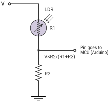
The most basic light sensor circuit consists of a photoresistor and a digital output interface, such as a transistor relay switch. A photoresistor is a type of resistor which varies its resistance in response to changes in the amount of light it receives. When the resistance of the photoresistor decreases, the current will increase, and vice versa. The current generated by the photoresistor can then be used to control a relay switch, which can be used to turn on a light or another electrical device.
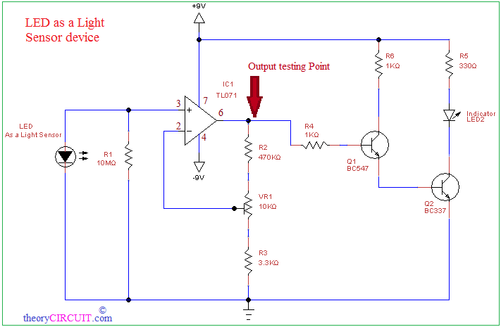
Other components such as transistors, operational amplifiers, and diodes can also be used in different configurations to create a light sensor circuit. Transistors can be used to amplify the voltage from the photoresistor and regulate its current, while an operational amplifier can be used to convert the current into a digital signal. Diodes are used for protection against overvoltage or reverse-polarity current.
Examples of Light Sensor Circuit Diagrams
Here are some examples of light sensor circuit diagrams, showing the different components involved in creating a working circuit. The diagram below shows a simple light sensor circuit using a photoresistor and relay:

In this circuit, the photoresistor acts as the sensing element, while the relay controls the load (in this case a lamp, but could be any other electronic device). The circuit works as follows: When the photoresistor receives light, its resistance decreases and more current flows through it. This causes the base voltage of the transistor to increase, turning it on, which in turn turns on the relay, and thus the lamp.
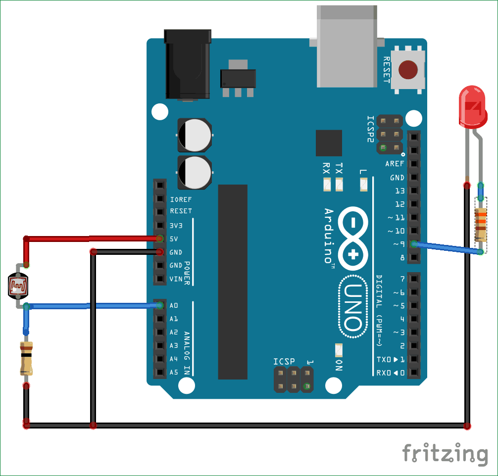
The following diagram shows a similar circuit, but this time using a transistor instead of a relay:

In this circuit, the transistor amplifies the current from the photoresistor and converts it into a digital signal. This signal can then be used to turn on or off a lamp or any other electrical device. This type of circuit is commonly used to automate lighting in homes and offices.
Conclusion
Light sensor circuits are simple but essential components in many electronic devices. This guide has discussed the basics of these circuits and presented some example diagrams. With this knowledge, you should now be able to understand and design your own light sensor circuits for any application.

Light Sensor Circuit

Ldr Circuit Diagram Build Electronic Circuits

Light Detector Circuit Using Wheatstone Bridge

Simple Light Sensor Circuit Without Ldr Using Bc549 Npn Transistor Circuitbest

Light Sensor Circuit Diagram Working And Its Applications

Led As A Light Detector Circuit

Light Sensor Circuit Page 3 Laser Led Circuits Next Gr

Arduino Light Sensor Circuit Using Ldr

Light Dark Sensor Using Lm393n Voltage Comparator Ic

Light Detector With Sensitivity Control Circuit

Light Sensors

Light Sensor Circuit Diagram Gadgetronicx

Ldr Circuit Diagram Build Electronic Circuits

Noa1213 Sensor Block Diagram Png Jpg Electronics Lab Com

Arduino Light Sensor Circuit Tutorial

How To Build A Dark Activated Light Circuit

Light Dark Sensor Using Lm358 Ic

Simple Light Sensor Circuit With Applications

Arduino Light Sensor Using Ldr Circuit Geeks

How To Build A Simple Sensor Module By Your Own Gadgetronicx
