Timing Diagrams for JK Flip-Flop Calculators: What They Mean and How to Use Them
Digital circuits use JK flip-flops to store and process binary bits of information. Timing diagrams are diagrams used to illustrate the timing of how the information is moved between different components of a digital circuit. Understanding a JK flip-flop timing diagram requires an understanding of the various concepts and components associated with the digital circuit in question. In this article, we will explore what a JK flip-flop diagram is and how it can be used to calculate timing information.
A JK flip-flop is a type of logic gate that is used to store and process binary bits of information. It has two inputs – known as “J” and “K” – and two outputs – known as “Q” and “Q”. The JK flip-flop can be used to create a wide range of digital circuits and can be used to perform a variety of tasks.
How a JK Flip-Flop Works
A JK flip-flop is made up of a pair of transistors, each connected to a power source. When the two inputs are both set to logic high (1), the output will be logic low (0). However, when one of the inputs is set to low (0) and the other is set to high (1), the output will be reversed, producing a logic high (1). In other words, when the inputs are both high (1) or both low (0), the output will remain unchanged.
The JK flip-flop is usually used in conjunction with a clock signal to control the flow of information through the circuit. This is done by “toggling” the outputs of the JK flip-flop according to the clock signal. When the clock goes high, the output of the JK flip-flop will change from one state to the other. This allows the circuit to process data quickly and accurately.
Interpreting JK Flip-Flop Timing Diagrams
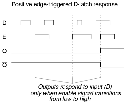
A JK flip-flop timing diagram is a graphical representation of the clock signals and output states for a given JK flip-flop. It shows the relationship between the clock signal, the input signals, and the output signals of the flip-flop. The diagram is usually divided into four parts – the clock signal, the JK inputs, the Q outputs, and the Q outputs.
The clock portion of the diagram shows how the clock signal rises and falls over time, while the input and output portions of the diagram show how the corresponding signals change in response to the clock signal. This can be used to determine how long a certain operation takes, or how quickly the circuit can respond to certain input signals.
Using a JK Flip-Flop Timing Diagram Calculator
To calculate the timings of a JK flip-flop, it is necessary to use a JK flip-flop timing diagram calculator. This is a specialized program which can be used to generate a timing diagram for a given circuit. By entering the necessary parameters into the calculator, it is possible to generate a timing diagram for the circuit and to calculate the timing details for the various operations that the circuit is capable of performing.
Using a JK flip-flop timing diagram calculator enables circuit designers to design more efficient circuitry. It can also be used to troubleshoot existing circuits and to analyze potential problems in the design. The calculator can also be used to estimate how long a certain task will take to complete, or to determine how much processing power is needed to perform certain tasks.
In conclusion, understanding JK flip-flop timing diagrams and using a JK flip-flop timing diagram calculator can make it easier for digital circuit designers to design more efficient and reliable circuitry. By understanding the relationships between the clock signal, inputs and outputs, it is possible to design more effective circuits, as well as to troubleshoot and optimize existing circuits.

Binary Count Sequence Instrumentationtools

Verilog Jk Flip Flop Javatpoint

Jk Flip Flop Preset Clear Inputs Truth Table Electronics Area

Flip Flops In Electronics T Flop Sr Jk D Circuits

Master Slave Flip An Overview Sciencedirect Topics

Solved The Jk Flip Flop 1 Figure Below Is A Timing Chegg Com

Edge Triggered Latches Flip Flops Instrumentationtools

Solved Do This Problem On Paper Complete The Timing Chegg Com

Jk Flip Flop Circuit Diagram Truth Table And Working Explained

Truth Table Of Jk Flip Flop Circuit Diagram And Master Slave Wira Electrical

Digital Circuits And Systems I Sistemes Digitals Csd Eetac Upc

Jk Flip Flop To Sr Conversion Sequential Logic Circuits Electronics Tutorial
Jk Flip Flop What Is It Truth Table Timing Diagram Electrical4u

Edge Triggered Latches Flip Flops Multis Electronics Textbook

Flip Flops Department Of It Sarita Nahak Lect

J K Flip Flop With Set Reset

Chapter5 Synchronous Sequential Logic Part 1 Ppt Online

