How To Calculate Amps In A Parallel Circuit

By | January 16, 2022


How To Calculate Amps In A Parallel Circuit


One of the most important topics in electrical engineering is the calculation of electrical current in a parallel circuit. This information is crucial for engineers, hobbyists, and home-owners alike, as it allows them to calculate how much current is flowing through each component of the circuit. Knowing this information can help ensure a safe and efficient electrical system, as well as preventing over-heating components that can lead to serious accidents.


Calculating the amount of current in a parallel circuit isn't necessarily a complicated process, but it does require an understanding of basic electrical principles. By taking into account the values of the resistors, capacitors, and other components in the circuit, the total current can be determined. In this article, we'll discuss the steps required to calculate the amps in a parallel circuit, as well as the advantages and disadvantages associated with this method.


Understanding Voltage and Resistance in a Parallel Circuit


The most important concept when calculating the amps in a parallel circuit is the understanding of voltage and resistance. To begin, it’s essential to note that the amount of current that passes through a conductor depends on the amount of voltage applied, as well as the amount of resistance the conductor has. The formula for Ohm’s law states that I = V/R, implying that current (I) equals voltage (V) divided by resistance (R).


When wiring a parallel circuit, it’s important to note that all components connected in a parallel circuit have the same potential difference–in other words, the same voltage. This means that each component has its own resistance, but they are all limited to the same voltage. As a result, components in a parallel circuit will always draw different amounts of current depending on their resistance values.


Calculating Amps With Kirchhoff's Voltage Law


Kirchhoff’s Voltage Law (KVL) is an equation that helps to calculate the total voltage in a circuit. This equation states that the sum of the total voltages around any given loop in a circuit must equal zero. In other words, if the voltage at one point in the circuit is higher than the voltage at another point, then the difference between those two points is equal to zero. This equation can be used to calculate the amount of current flow in a parallel circuit.


The KVL equation states that the sum of the voltage drop and voltage rise across the loop must equal zero. To calculate the current in a parallel circuit, the equation must be rearranged to solve for the current. Once the equation is rearranged, all that is needed is a value of voltage and resistance for each component in the circuit to solve for the current. This method is advantageous because it gives you a quick and accurate calculation of the total current.


Advantages & Disadvantages


Calculating the amps in a parallel circuit using the KVL equation is an effective way to get an accurate result. This method is advantageous for quickly calculating the total current, which is essential for many electrical engineering tasks. Additionally, it doesn’t require the use of specialized software or complicated calculations, making it a user-friendly option.


On the downside, the KVL equation can become complicated when dealing with complex circuits. Additionally, it’s not always possible to accurately measure the voltage and resistance of each component. This could lead to incorrect total current calculations, which can lead to serious problems such as overloading components or even electric shock.


Conclusion


Calculating the amps in a parallel circuit is essential for any electrical project. Although there are some drawbacks to using the KVL equation for this task, it’s overall an effective method for quickly and accurately calculating the total current. By taking into account the voltage and resistance of each component in the circuit, the KVL equation can be used to get an accurate result. Understanding this equation and its applications can help anyone working with electrical systems to become safer and more efficient.


11 2 Parallel Circuits Series And Siyavula

11 2 Parallel Circuits Series And Siyavula


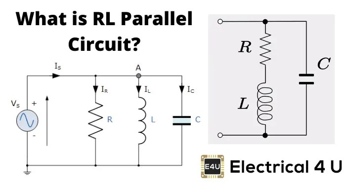
Rl Parallel Circuit Electrical4u

Rl Parallel Circuit Electrical4u


Solved R1 10 R3 R4 12 2 Parallel Series Circuit Above A Chegg Com

Solved R1 10 R3 R4 12 2 Parallel Series Circuit Above A Chegg Com


Simple Parallel Circuits Series And Electronics Textbook

Simple Parallel Circuits Series And Electronics Textbook


How To Calculate Amperage In A Series Circuit

How To Calculate Amperage In A Series Circuit


Paralleling Amplifiers Increases Output Drive Analog Devices

Paralleling Amplifiers Increases Output Drive Analog Devices


Simple Parallel Circuits Series And Electronics Textbook

Simple Parallel Circuits Series And Electronics Textbook


Series And Parallel Circuits Learn Sparkfun Com

Series And Parallel Circuits Learn Sparkfun Com


How To Solve Parallel Circuits 10 Steps With Pictures Wikihow

How To Solve Parallel Circuits 10 Steps With Pictures Wikihow


Simple Parallel Circuits Series And Electronics Textbook

Simple Parallel Circuits Series And Electronics Textbook


Simple Parallel Circuits Series And Electronics Textbook

Simple Parallel Circuits Series And Electronics Textbook


Difference Between Series And Parallel Circuits Javatpoint

Difference Between Series And Parallel Circuits Javatpoint


How To Calculate The Cur That Flows Through A Parallel Circuit In Relation Resistance Diffe Branches Quora

How To Calculate The Cur That Flows Through A Parallel Circuit In Relation Resistance Diffe Branches Quora


Cur Through Resistor In Parallel Worked Example Khan Academy

Cur Through Resistor In Parallel Worked Example Khan Academy


Physics Tutorial Parallel Circuits

Physics Tutorial Parallel Circuits


Complex Circuit Stickman Physics

Complex Circuit Stickman Physics


Series And Parallel Circuits Learn Sparkfun Com

Series And Parallel Circuits Learn Sparkfun Com


Solving Problems 14 1 A Circuit Contains 5 Ohm 3 And 8 Resistors In Series What Is The Total Resistance Of Rt R1 Ppt

Solving Problems 14 1 A Circuit Contains 5 Ohm 3 And 8 Resistors In Series What Is The Total Resistance Of Rt R1 Ppt


Electrotech Text Alternative

Electrotech Text Alternative