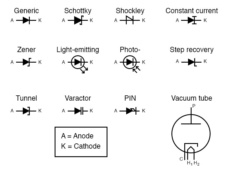
Understanding Electrical Circuit Drawing Symbols & How They Help in Design
Throughout the world of electronics, electrical circuit drawing symbols are an incredibly valuable tool. Whether you are a student, a professional engineer, or a hobbyist, understanding how each type of symbol works can help improve the accuracy of design and reduce overall design time. In this article, we will discuss the different types of electrical circuit drawing symbols, their meanings and how they are used in the design process.
Types of Electrical Circuit Drawing Symbols
There are three main types of symbols commonly used in electrical circuit diagrams: physical components, logic gates and connection relays. The physical components, such as resistors, capacitors, and transistors, are represented by the corresponding physical form (eg. the schematic representation of a capacitor is a parallel-lined oval). Logic gates are digital components, represented by the use of special graphical designs (eg. AND, OR, NOT) and connection relays are generally represented by arrows connecting two points.
Specific Symbols and Their Usage
For example, a resistor symbol typically consists of a short line parallel to a longer line, with a gap between the two lines indicating the resistance value. A capacitor symbol typically consists of two parallel lines with a small gap between them, indicating the capacitance value. A transistor symbol consists of three lines, typically indicating the base (B), collector (C) and emitter (E) pins. And a logic gate typically consists of a series of arrows and lines, indicating the specific logical operation (AND, OR, NOT, etc).
Using Electrical Circuit Drawing Symbols
Electrical circuit drawing symbols are used to create a schematic diagram of an electrical circuit. A schematic diagram is a comprehensive set of visual instructions for wiring a circuit, and can be used to troubleshoot any errors that may occur in the circuit. When building a circuit, it’s important to follow the schematic diagram closely, paying attention to the various symbols used and their meanings. Understanding the symbols and their meanings is crucial to creating an effective and accurate circuit diagram.
Conclusion
In summary, electrical circuit drawing symbols are an essential tool for designing and creating electrical circuits. They provide a standardized way of expressing instructions — which drastically reduces the amount of time needed for the design process. With a basic understanding of these symbols, anyone can begin to understand circuit diagrams and create effective and accurate circuits.

Why Do We Need Electrical And Electronic Symbols Are Important Automation Plc Programming Scada Pid Control System
Circuit Diagram Mydraw

Electrical Schematic Symbols Lesson Transcript Study Com

Schematic Symbols Learn Parallax Com
Typical Electrical Drawing Symbols And Conventions

Schematic Circuit Diagram Powerpoint Slide Slidemodel

Ss Electric Circuits And Symbols Mini Physics Learn

Wiring Diagram Schematic Electrical Engineering Electronic Symbol Circuit Png 1800x1500px Area Brand

Simple Electrical Circuits

Types Of Electrical Schematic Symbols With Explanation At A Glance

Electrical Symbols Try Our Symbol Softe Free

Electrical Schematic Symbols Names And Identifications

Drawing Circuits For Kids Physics Lessons Primary Science

Diodes Circuit Schematic Symbols Electronics Textbook

Royalty Free Vector Electric And Electronic Circuit Diagram Symbols Set Of Electrical Instrumentation Meters Recorders By Vermicule

Electrical Symbols Diagram
Most Important Electrical Wiring Diagram Symbols Etechnog

Circuit Schematic Symbols Atmega32 Avr

Electricity Circuits Symbols
Most Important Electrical Wiring Diagram Symbols Etechnog


