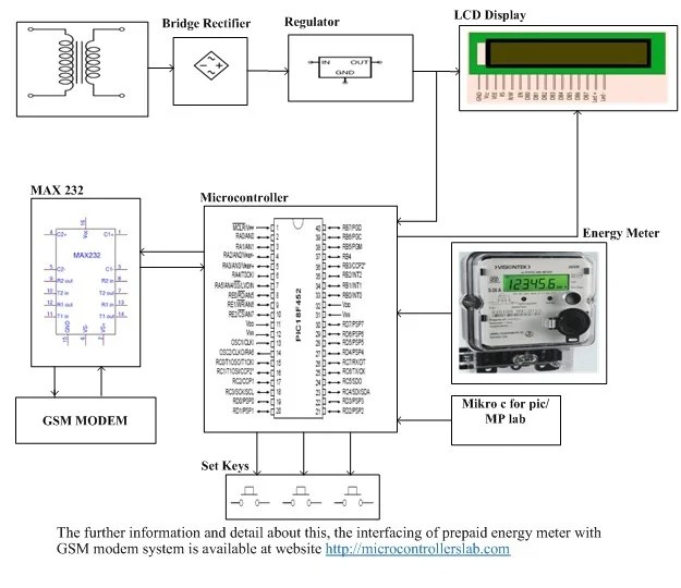
Understanding The Electrical Meter Circuit Diagram For Your Home
The electrical meter circuit diagram is one of the most vital pieces of equipment in your home. It provides a means to measure electricity use, identify potential problems, and take steps towards a more efficient use of energy. Understanding how to read the diagram accurately can save you both time and money in the long run.
Having an understanding of electricity and electrical components is necessary when working with an electrical meter circuit diagram. It’s important to obtain an up-to-date version of the diagram from your local utility company or from the manufacturer so that all the current wiring and devices are accounted for.
Understanding the Basics of the Electrical Meter Circuit Diagram
At its most basic, an electrical meter circuit diagram is a visual representation of the components and wiring between the various devices in a home. It shows the arrangement of outlets, switches, fuses, and other components. It also helps to identify which type of device is what, making it easier to trace and fix problems.
One key feature of the electrical meter circuit diagram is that each device should be labeled. This helps to ensure that each component is correctly identified, preventing confusion and potential accidents. All labels should be clearly visible on the diagram as they are used to quickly identify each component.
Safety Precautions When Working with an Electrical Meter Circuit Diagram
Safety is paramount when dealing with electricity and an electrical meter circuit diagram. Before starting any repairs or maintenance, it is essential to fully understand the risks involved and take the appropriate safety precautions.
It is always recommended that you wear protective clothing such as gloves, long sleeves, and long trousers, as well as eyewear and a face mask to protect against dust, sparks, and other hazards. Additional tools such as voltage testers and insulated screwdrivers may also be needed to carry out the work safely.
Maintenance Tips for an Electrical Meter Circuit Diagram
With proper maintenance, an electrical meter circuit diagram can help to keep your home running efficiently. Some handy tips for keeping the diagram in good condition include:
- Checking for loose connections and replacing any broken cables
- Cleaning the circuit board regularly with a dry cloth
- Ensuring all terminals are tight and undamaged
- Limiting the number of power strips plugged into one outlet
- Using surge protectors to protect against power surges
As devices become outdated or are replaced, they should be removed from the diagram to ensure accuracy. In the same way, if new wiring or devices are installed, they should be added to the diagram to ensure that the wiring is correct and up to date.
The Benefits of an Accurate Electrical Meter Circuit Diagram
An accurate and up-to-date electrical meter circuit diagram is invaluable in helping to identify potential problems and take steps towards a more efficient use of energy. By identifying faulty wiring and unsafe practices, the diagram can help to reduce the risk of fires and other accidents caused by electricity.
Furthermore, an accurate diagram is essential for identifying any saving opportunities and implementing them. Installing motion sensors, using smart thermostats, and ensuring that all appliances are energy efficient can all help to reduce your energy costs.
In conclusion, an accurate and well-maintained electrical meter circuit diagram is an invaluable tool for any homeowner. With a little bit of knowledge and careful maintenance, it can help to keep your home safe and your energy bills low.

Calibration Of Energy Meter Definition Procedure Diagram Electricalworkbook

Prepaid Energy Meter Project Using Gsm And Pic Microcontroller
What Is The Circuit Diagram For Digital Electricity Meter Quora

Wiring Diagrams

Wiring Diagrams

Prepaid Energy Meter Project Using Arduino

Energy Meter Working Construction Diagram Electricalworkbook

Circuit Diagram Of Prepaid Energy Meter Scientific

Circuit Diagram Of Prepaid Energy Meter Scientific

所有电子动力和电表 亚德诺半导体

Energy Meter Using The Maxq3180 Maxq3183 Maxim Integrated

The Schematic Diagram Of Electrical Smart Meter Scientific

3 Phase Energy Meter Circuit Diagram The Diy Life

Metering Energy Monitoring Analog Devices

Energy Meter Circuit

Tidm Metrology Host Reference Design From Texas Instruments

Results Page 276 About Digital Energy Meter Circuit Searching Circuits At Next Gr

Forums Project Doubts Prepaid Energy Meters Rickey S World Of Microcontrollers Microprocessors

Construction Of Ac Energy Meter Electrical4u
