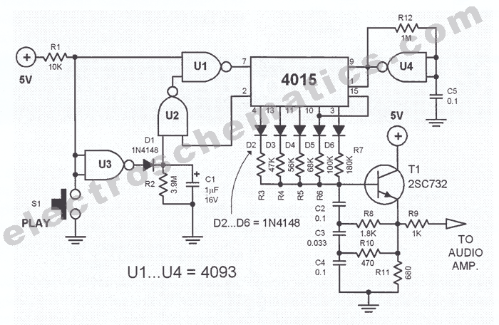
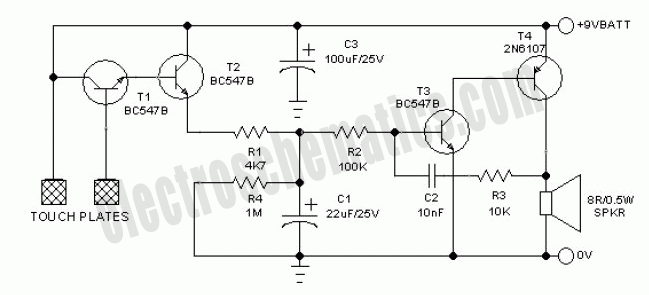
Understanding The Circuit Diagram Of Doorbell Alarm
Do you have any idea how a doorbell alarm works and what is going on behind the scenes? Have you ever taken the time to look at a circuit diagram for a doorbell alarm and seen how all the different parts work together? Understanding the circuit diagram of a doorbell alarm is essential if you want to get the most out of it. In this article we will look at some of the key components in a doorbell alarm and how they work together to create a reliable security system.
Types of Doorbell Alarm Circuits
There are several types of doorbell alarm circuits that can be used depending on the application. The two most common alarm circuits are the wired alarm and the wireless alarm. Wired alarms are connected directly to the power supply and consist of a doorbell button, a chime box, a transformer, and an electric relay switch. These components play an important role in creating the sound of the alarm when someone pushes the doorbell button. On the other hand, wireless alarm systems use radio frequency signals to send signals to the chime box. This type of alarm system can be more difficult to install, but it is more reliable.
Components of a Doorbell Alarm Circuit
A doorbell circuit consists of several components that work together to make the alarm sound when activated. The components of a typical doorbell alarm circuit are:
- Chime box – This is the device that produces the sound of the alarm when the doorbell is pushed.
- Relay switch – This is an electronic device that controls the flow of electricity and opens and closes when triggered by a signal from the doorbell.
- Transformer – This is an electrical device that transforms the voltage coming from the power source into an appropriate voltage for the doorbell.
- Power source – This is the source of electrical power for the entire system.
How the Circuit Works
When the doorbell button is pressed, a small current is sent straight to the chime box. This makes the chime box produce a loud noise as the alarm. The current then passes through the relay switch, which triggers the transformer and increases the voltage to match the power source. This energizes the relay switch, which will remain open until the alarm is reset.
The current then passes through the transformer, which reduces the voltage back to the original voltage of the doorbell. The current then travels back through the relay switch and eventually to the chime box, which will stop making the sound of the alarm. This process is repeated each time the doorbell button is pushed.
Using a Doorbell Alarm Circuit
When it comes to using a doorbell alarm, there are several steps that should be taken. First, it is important to make sure that all of the components are properly connected and that no loose wires or connections exist. Next, it is important to test the system to make sure it is working properly before leaving it in place. Lastly, it is important to regularly check the system to ensure that it is still functioning correctly.
Understanding the circuit diagram of a doorbell alarm is essential for anyone who is looking to purchase or install one. By taking the time to understand the components and how they work together, you can ensure that your doorbell alarm system is reliable and secure.

Musical Doorbell Circuit

Doorbell Wiring Diagrams

Doorbell For The Deaf Circuit Diagram And Instructions
Fridge Door Alarm 2nd Version Red Page99

Doorbell Security System Detailed Electronics Circuit

Doorbell Memory Circuit Diagram And Instructions

Doorbell Circuit Page 2 Other Circuits Next Gr

Simple Touch Doorbell Alarm Circuit Diagram Using Transistor Without Ic

Doorbell Wiring Diagrams

How To Install An Alarm Com Vdb770 Surety Support Forum

Simple Touch Alarm Circuit

Simple Musical Door Bell Circuit Homemade Projects

How To Build A Door Alarm Circuit

Security Alarm Circuit With High Power Siren Diagram And More

How A Wired Doorbell Works Hometips

Electronic Doorbell With Light

Door Knock Sensing Doorbell Using Piezoelectric

Simple Touch Alarm Circuit
