03010 wireless security system camera transmitter schematics schematic diagram marasst orporation wire cctv online 56 off www ingeniovirtual com cc factory 55 not working how to fix it learn mega idea wiring for facebook layout network example and access plans electronic closed circuit television ip electrical wires cable light pole png pngegg 5 very simple steps on install cameras homeowners android rg59 siamese coax guide analog hd om work nvr connection mod computer code angle electronics pngwing control unit scientific an2487 reference design dc multi output power supplies arrow adapter worldeyecam is data precision ccd 701 dagram jsw pacific of multilayer pcb china made in 3 ways a house wikihow create professional diagrams daisy chain topology installation with connect tatco syr services imp exp connectible image 21 presentation categories what the monitoring which can record dipol ireland 2 1 0 cctvwiringdiagram learning ideas draft copy conceptdraw pro softe surveillance pdf more about umoval dvr kit basic diagramming audio configurations unkle s infotech centre home poe injectors wifi bridges router securitycamcenter chapter page telecommunications handbook transportation professionals controller free cad block drawing based automatic traffic cat crossover options 1181x966px closedcircuit bewakingscamera brand
03010 Wireless Security System Camera Transmitter Schematics Schematic Diagram Marasst Orporation

Wire Cctv Camera Online 56 Off Www Ingeniovirtual Com

Cc Camera Wire Factory 55 Off Www Ingeniovirtual Com

Cctv Camera Not Working How To Fix It Learn Com
Mega Idea Wiring Diagram For Cctv System Facebook

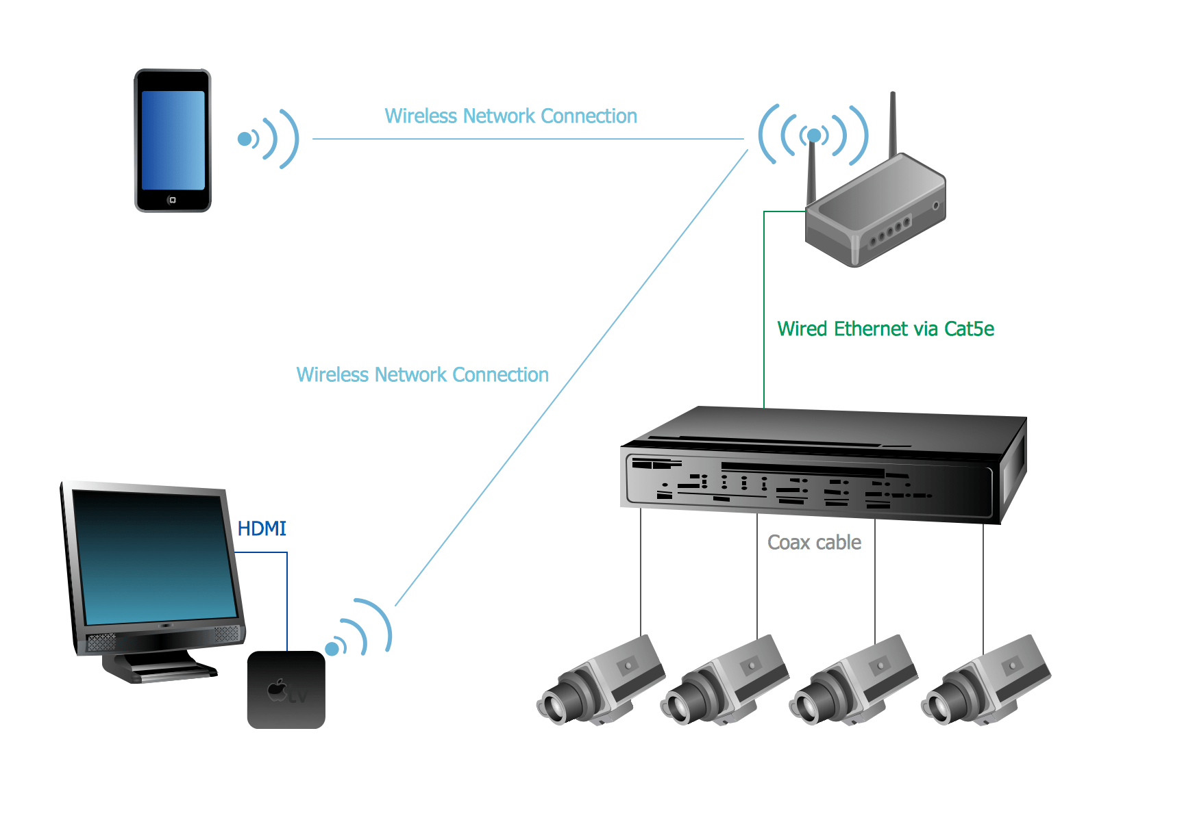
Camera Layout Schematic Cctv Network Example Security And Access Plans Electronic

Closed Circuit Television Wiring Diagram Wireless Security Camera Ip Electrical Wires Cable Light Pole Schematic Png Pngegg

Wiring Diagram For Cctv System
5 Very Simple Steps On How To Install Cctv Cameras For Homeowners

Cctv Camera Wiring Diagram For Android

Rg59 Siamese Coax Cable Wiring Guide For Analog Cctv Cameras Hd Security
Om Electrical Work Nvr Ip Cctv Camera Connection Diagram Facebook

Cctv Camera Mod Schematic

Camera Layout Schematic Cctv Network Example Security And Access Plans Electronic

Ip Camera Closed Circuit Television Wiring Diagram System Computer Network Code Angle Electronics Schematic Png Pngwing

Control Unit Circuit Diagram Scientific

An2487 Reference Design Dc To Multi Output Power Supplies Arrow Com

Camera Cable And Power Adapter Connection Diagram Worldeyecam

Cctv System Is Data Precision

Cctv Camera Wiring Diagram For Android
03010 wireless security system camera transmitter schematics schematic diagram marasst orporation wire cctv online 56 off www ingeniovirtual com cc factory 55 not working how to fix it learn mega idea wiring for facebook layout network example and access plans electronic closed circuit television ip electrical wires cable light pole png pngegg 5 very simple steps on install cameras homeowners android rg59 siamese coax guide analog hd om work nvr connection mod computer code angle electronics pngwing control unit scientific an2487 reference design dc multi output power supplies arrow adapter worldeyecam is data precision ccd 701 dagram jsw pacific of multilayer pcb china made in 3 ways a house wikihow create professional diagrams daisy chain topology installation with connect tatco syr services imp exp connectible image 21 presentation categories what the monitoring which can record dipol ireland 2 1 0 cctvwiringdiagram learning ideas draft copy conceptdraw pro softe surveillance pdf more about umoval dvr kit basic diagramming audio configurations unkle s infotech centre home poe injectors wifi bridges router securitycamcenter chapter page telecommunications handbook transportation professionals controller free cad block drawing based automatic traffic cat crossover options 1181x966px closedcircuit bewakingscamera brand


