What You Need to Know About ANSI Standard Electrical Schematic Symbols
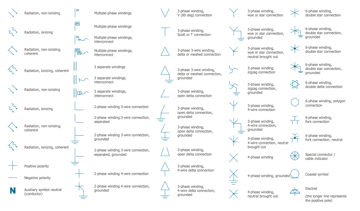
Electrical schematics are diagrams that represent the components and wiring of a circuit. They show how different components of the circuit interact with each other, and the physical locations of the components used in the circuit. In order for a circuit to be properly understood and maintained, it is important that a standard notation is used. This is where ANSI standard electrical schematic symbols come into play.
ANSI stands for American National Standards Institute, and they publish many standards that are used in a variety of industries. It is their electrical symbols standard, officially known as Y32.2-1975 or IEEE 315-1975, that has become the international standard for electrical diagrams. This standard defines the shapes and sizes of the symbols used on most electrical schematics.
How Symbols Help Read Electrical Schematics
There are countless parts and connections that appear on an electrical schematic, making them often messy and hard to understand. As new technologies are developed and new components are introduced, the complex network of connections presented in a typical circuit can be overwhelming. Having a universal language of symbols allows for a more efficient understanding of the circuit. Each component will be represented by an ANSI symbol, so a reader would not have to decipher complex code.
The process of reading and interpreting an ANSI electrical schematic is actually quite simple. Each component on the schematic is represented by a different symbol. This will allow the user to quickly identify a component without having to know any specific technical information about it. By connecting the symbols together and following the flow of electricity, one can quickly understand the workings of the circuit.
The Different Components and Their Symbols
The ANSI standard outlines the symbols for over 200 components, such as switches, relays, motors and wires. These symbols are typically connected with a line indicating the flow of electricity between components. The standard also defines the size and layout of the symbols, which helps to ensure a consistent look and feel across different drawings.
The most common symbols are those for basic electrical components, including resistors, capacitors and inductors. More advanced components, such as transistors, diodes and integrated circuits, will also have a unique symbol. These symbols are specifically designed to be easily recognized, even by those unfamiliar with the technical aspects of the components.
The Benefits of Using Ansi Standard Electrical Schematic Symbols
Using standard ANSI symbols to represent components in an electrical schematic has numerous benefits. As mentioned earlier, it allows a user to quickly identify a component even if they aren’t familiar with it. This saves time when troubleshooting a circuit or when providing maintenance.
The use of ANSI symbols also makes it easier for different people to communicate. Most technicians, engineers and students will be familiar with the symbols, allowing for easier discussions about a circuit. This makes it easier to collaborate and share ideas when working on a project.
Finally, using a standard set of symbols ensures that electrical schematics are drawn consistently. This helps to ensure that they can be read and understood quickly, making a circuit easier to troubleshoot, maintain and modify.

Solidworks Electrical Parts Creation

Learn Hv Substation Elements Graphic Symbols Basics Connection Schemes Eep

Graphic Symbol An Overview Sciencedirect Topics
Nema And Iec Schematic Diagram Comparisons Mz081001en

The Essentials Of Designing Mv Lv Single Line Diagrams Symbols Drawings Analysis Eep

Ul Csa Symbols Jic Or Iec Autodesk Community Electrical
Ansi Standard J Std 710
Typical Electrical Drawing Symbols And Conventions

Ansi Standard J Std 710 Architectural Drawing Symbols Bedrock Learning

The Electrical Information And Layouts In Construction Drawings
Nema And Iec Schematic Diagram Comparisons Mz081001en
Who Invented The Various Circuit Symbols In An Electrical Quora

Intro To Relays 2 Ansi Ieee Relay Numbers

What Are Schematic Symbols Digikey

Electrical Symbols Qualifying

Electrical Symbols Qualifying

What Is The Meaning Of Schematic Diagram Sierra Circuits

Electrical Schematic Design Softe E3 Zuken Us

Item Designations Or Why Are Relays Called K In Schematics Circuit Breakers Q
