Everything You Need to Know About And Gate Transistor Diagrams
Understanding how an And Gate Transistor works is critical to the modern electronics industry. It's the fundamental building block of computers and other electronic devices, enabling them to process and store information in a reliable and efficient manner. But what exactly is an And Gate Transistor and how does it work? Let’s take a closer look at what an And Gate Transistor Diagram is and how it functions.
An And Gate Transistor Diagram is a schematic diagram that shows the different types of transistors and how they interact with each other. It can also be used to show how many transistors are required to create a particular logic gate. Logic gates are what make computers and other electronic devices function the way they do. In this article, we will discuss how an And Gate Transistor Diagram works and why it is so important to the modern electronics industry.
The Basics of an And Gate Transistor
A transistor is a component made up of three terminals: the source, drain, and gate. The source is the area where electricity enters the transistor, while the drain is the area where electrons leave the transistor. The gate acts as a switch or an amplifier, allowing current to flow either through or away from the transistor depending on the voltage applied to it.
An And Gate Transistor is one type of logic gate that is used to control how much current flows through the transistor. It operates by setting up two sets of voltage levels, a high voltage and a low voltage. When both the high voltage and the low voltage are present, current passes through the transistor, but when only one of the two voltages are present, the transistor does not allow any current to pass.
Creating an And Gate Transistor Diagram
In order to create an And Gate Transistor Diagram, you must determine the number of transistors required to create a particular logic gate. This can be done by using a standard logic circuit diagram. Once you have determined the number of transistors required, you can then draw the And Gate Transistor Diagram. It is important to remember that the number of transistors required to create a particular logic gate is fixed and cannot be changed.
When creating an And Gate Transistor Diagram, the most important part is to ensure that all transistors line up properly with one another. In order for the circuit to work correctly, it must be constructed properly. Careful attention must be paid to how the transistors are arranged and connected in order for the circuit to function properly.
The Benefits of an And Gate Transistor Diagram
An And Gate Transistor Diagram is an invaluable tool in the modern electronics industry. By having a better understanding of how these circuits work, engineers are able to design more efficient and reliable systems. In addition, these diagrams provide greater insights into how certain logic gates interact with each other, making it easier to troubleshoot and repair any problems that may arise in the future.
Furthermore, And Gate Transistor Diagrams are often used to create complex logic gates that are used in advanced applications. These diagrams provide a visual representation of the relationships between the various transistors and their associated voltages, ensuring that the circuit functions in the way that it was designed. As such, these diagrams are incredibly useful and can be used to help develop new technologies.
Overall, And Gate Transistor Diagrams are essential to the modern electronics industry. They provide a better understanding of how these circuits operate, helping engineers design and troubleshoot more effectively. In addition, these diagrams help to create more complex logic gates for advanced applications, making them invaluable to the electronics industry.

Logic03 Gif

How To Use Digital Logic In Electronic Circuits Circuit Basics

Draw The Circuit Diagram Of Ttl Nand Gate And Explain Class 12 Physics Cbse

Bipolar Xor Gate With Only 2 Transistors Details Hackaday Io
My Computer Assistant Logic Gates Are The Base Of Some Gate Circuit Showing Its Working A Very Useful Project For Student Physics Building

B Electronics Projects How To Create A Transistor Nand Gate Circuit Dummies

Nand Inverter Circuit Diagram Simple Free Not Gate Transistor Transpa Png 1200x1200 On Nicepng

From Transistors To Gates

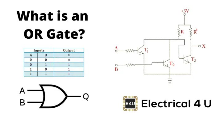
Or Gate What Is It Working Principle Circuit Diagram Electrical4u

A Transistor Circuit Of 3 Input Nand Gate B Excitation For Arc A3 X Scientific Diagram

And Gate Using Transistor

Logic Gates Building Blocks Of Digital Circuits De Part 4
Chapter 15 Cmos Digital Logic Circuits

Or Gate What Is It Working Principle Circuit Diagram Electrical4u

B Digital Electronics Integrated Circuit Logic Gates Dummies

Nor Gate Truth Table Symbol 3input Circuit Diagram Ic

Npn Transistor Xor Gate Circuit Sully Station Technologies

Or Gate

And Gate Transistor Level Schematic Scientific Diagram

The Not Gate Logic Gates Electronics Textbook

