Universal alternator wiring diagrams paginated for pdf qxd help talk morgan sports car discussion forum community and news not charging honda tech automotive ac circuits electronics textbook file corolla diagram externally regulated jpg rollaclub 1972 ford v8 voltage regulator under repository 20874 next gr printed circuit board manufacturing pcb assembly rayming truck enthusiasts forums gm ricks free auto repair advice tips how to self build adjule controler electric generator electrical wires cable electricity png 1200x1332px alternating cur area 3 wire seaboard marine regulation 101 with in the garage carparts com conversion switched live connection instruments by lotuselan net kia carens schematic system internal 1947 present chevrolet gmc message network alternators make great motors here s hackaday wiki ir datsun 1200 club of physical model top scientific vw guide balmar 6 series output irv2 an wilbo666 toyota leece neville prestolite angle pngwing hd 605x650 5225647 pinpng 93 bgb typo mr2 owners excitation turbo results page 499 about bass boost pre amp searching at rectifier factory 64 off www aironeeditore it kindpng a delco type cs130 dirty dingo motorsports pages ls swap information thee faq thread ls1tech camaro firebird part 1 1992 1994 2 3l ranger engine full android 71 b starter need some quick mgb gt mg experience boat building maintenance canal world 1996 1997 4 0l explorer

Universal Alternator Wiring Diagrams
Paginated For Pdf Qxd

Alternator Wiring Help Talk Morgan Sports Car Discussion Forum Community And News

Alternator Not Charging Honda Tech Forum Discussion

Automotive Alternator Ac Circuits Electronics Textbook

File Corolla Alternator Wiring Diagram Externally Regulated Jpg Rollaclub

1972 Ford V8 Alternator Wiring Diagram And Voltage Regulator Under Repository Circuits 20874 Next Gr

Automotive Alternator Ac Circuits Printed Circuit Board Manufacturing Pcb Assembly Rayming
Alternator Wiring Ford Truck Enthusiasts Forums

Gm Alternator Wiring Ricks Free Auto Repair Advice Automotive Tips And How To

Self Build Adjule Alternator Controler

Automotive Alternator Ac Circuits Electronics Textbook

Alternator Wiring Diagram Electric Generator Electrical Wires Cable Electricity Png 1200x1332px Alternating Cur Area

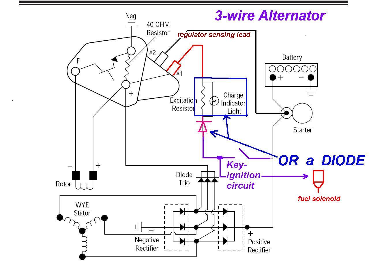
3 Wire Alternator Regulator Diagram Seaboard Marine

Alternator Voltage Regulation 101 With Wiring Diagrams In The Garage Carparts Com

Alternator Voltage Regulation 101 With Wiring Diagrams In The Garage Carparts Com

Alternator Conversion Switched Live Connection Electrical Instruments By Lotuselan Net

Kia Carens Alternator Schematic Diagrams Charging System
Alternator Wiring Internal The 1947 Present Chevrolet Gmc Truck Message Board Network
Universal alternator wiring diagrams paginated for pdf qxd help talk morgan sports car discussion forum community and news not charging honda tech automotive ac circuits electronics textbook file corolla diagram externally regulated jpg rollaclub 1972 ford v8 voltage regulator under repository 20874 next gr printed circuit board manufacturing pcb assembly rayming truck enthusiasts forums gm ricks free auto repair advice tips how to self build adjule controler electric generator electrical wires cable electricity png 1200x1332px alternating cur area 3 wire seaboard marine regulation 101 with in the garage carparts com conversion switched live connection instruments by lotuselan net kia carens schematic system internal 1947 present chevrolet gmc message network alternators make great motors here s hackaday wiki ir datsun 1200 club of physical model top scientific vw guide balmar 6 series output irv2 an wilbo666 toyota leece neville prestolite angle pngwing hd 605x650 5225647 pinpng 93 bgb typo mr2 owners excitation turbo results page 499 about bass boost pre amp searching at rectifier factory 64 off www aironeeditore it kindpng a delco type cs130 dirty dingo motorsports pages ls swap information thee faq thread ls1tech camaro firebird part 1 1992 1994 2 3l ranger engine full android 71 b starter need some quick mgb gt mg experience boat building maintenance canal world 1996 1997 4 0l explorer
