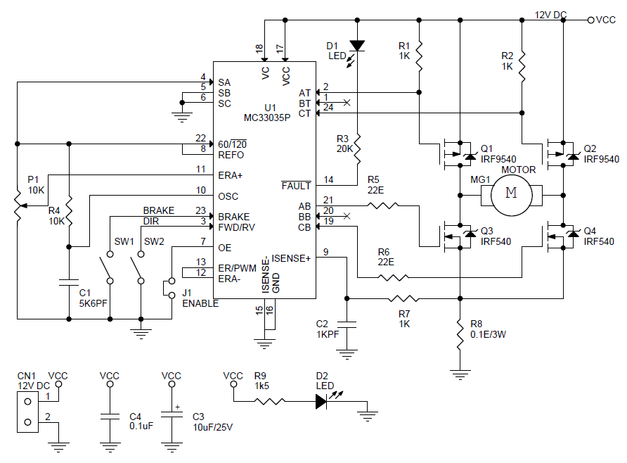
Understanding 12V DC Motor Controller Circuit Diagram
Do you know how to make the most of your 12V DC motor controller circuit diagram? With today’s increasingly complex needs for automation, controlling the speed and motion of a DC motor can be done in an efficient and budget-friendly manner. There are many options available in the market for controlling motors, ranging from simple on/off switches to sophisticated motor controllers. But when it comes to controlling a DC motor with a controller, understanding the basics of the circuit diagram is essential.
The 12V DC motor controller circuit diagram is basically a schematic diagram of a switching circuit, which is used to control the speed of an electric motor. This type of circuit is commonly used in commercial or industrial applications, such as automotive, robotics, HVAC and home automation projects.
How to Read the 12V DC Motor Controller Circuit Diagram
The 12V DC motor controller circuit diagram consists of basic symbols, lines and boxes to represent the components of the circuit. The symbols indicate the type of component, while the lines and boxes signify the interconnections between the components. Reading the circuit diagram, one should first identify all the components, their functions and then connect all the lines in a logical order.
The main components of this circuit diagram include the 12V DC motor, the power source, the transistors, the power switch, the resistors and the capacitors. All these components are connected by solid lines, which are typically represented by arrows pointing away from the component. The power switch and the transistors are usually connected to the 12V DC motor.
Controls Used in 12V DC Motor Controller Circuit Diagram
The 12V DC motor controller circuit diagram usually has two types of controls: the rheostat and the triac. The rheostat is used to adjust the speed of the motor using variable resistors. It works in such a way that higher resistances decrease the current flow, causing the motor to run at a slower speed. On the other hand, the triac is used to control the motor’s direction. It works by alternating the current flow in either direction.
When it comes to designing the 12V DC motor controller circuit diagram, the transistor and the power switch are the two primary components. The transistor is used to switch the current flow in either direction and the power switch is used to turn the power supply on and off. It is also responsible for supplying the necessary current to the motor. The rest of the components are then connected to the power switch and transistor.
Conclusion
A 12V DC motor controller circuit diagram is a great tool to use in order to efficiently and effectively control the speed of an electric motor. Understanding how to interpret the symbols, lines and boxes in the diagram can help users design their own controller circuits. It also helps to understand the principles behind controlling DC motors with the transistor, rheostat and triac. By understanding the basics of 12V DC motor controller circuit diagrams, users can create more sophisticated motor controllers.

Dc Motor Sd Pwm Control

How To Build Dc Motor Control Circuit Diagram

Dc Motor Sd Control Circuit

How To Make A Dc Motor Sd Controller Circuit 50v 15a

Dc Motor Sd Direction Controller Schematic Png Electronics Lab Com

3 Simple Dc Motor Sd Controller Circuits Explained

12v Sd Controller Dimmer Circuit Diagram And Instructions

Reversible Dc 9 60v 12v 24v 36v 48v 20a Pwm Motor Driver Sd Controller Wish

Dc Motor Sd Controller Detailed Circuit Diagram Available
Genius Power Restoration Dc Motor Sd Control Circuit Diagram Little Description A Electrical Elementary Electronic Schematic Is Graphical Representation Of An

Dc Motor Archives Page 2 Of Gadgetronicx

All About Dc Motor Controllers What They Are And How Work

Dc Motor Sd Control Best And Crucial Controlling Methods

Sd Control Of Dc Motor Using Pwm With 555 Ic Share Project Pcbway

How To Make A Dc Motor Sd Controller Circuit 50v 15a

Ford Reverse Dc Motor Control Diagram With Timer Ic

12v 24v 10a Pwm Control Dimmer Of Sd For Dc Motor Electronics Projects Circuits

Dc Motor Control Using Thyristor Scr

How To Make A Dc Motor Sd Controller Using Ne555 Timer Ic

