Single channel relay sch png electronics lab com how to make module circuit and pcb earn money dip 5v pinout working interfacing applications set up a on the arduino basics 16 channels for raspberry pi pic avr control tutorial with code diagram driving esp 01 project guidance forum optocoupler latest 3 dc 3v expansion board insulation dual specification application datasheet 4 wiki do i switch low level using r esp8266 lesson 22 1 osoyoo pin specifications 2 driver design configuration its search easyeda four open source harde mc controlling an esp32 diy 6 steps pictures instructables in depth interface two aptofun hd high voltage devices transpa image nicepng battery operated power supply other components scientific one trouble running microcontrollers compre aa bb supports trigger barato frete grátis avaliações reais fotos joom 8 onboard regulator switching 12vdc led indicator lamp through ledultiplexing 12v water pump controlled by won t work 28 system motors mechanics cnc

Single Channel Relay Sch Png Electronics Lab Com

How To Make Relay Module Circuit And Pcb Earn Money Dip Electronics Lab

5v Single Channel Relay Module Pinout Working Interfacing Applications

How To Set Up A 5v Relay On The Arduino Circuit Basics

Relay Module 5v 16 Channels For Raspberry Pi Arduino Pic Avr

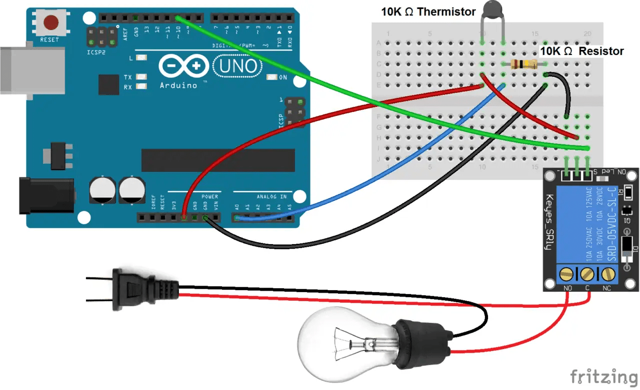
Arduino Relay Control Tutorial With Code And Circuit Diagram

Driving 5v Relay With Esp 01 Project Guidance Arduino Forum

Project How To Make A Relay Module With Optocoupler Latest Circuit Diagram Dip Electronics Lab

3 Channel Dc 3v 5v Relay Module Expansion Board With Optocoupler Insulation For Arduino

5v Dual Channel Relay Module Pinout Specification Application Working Datasheet

4 Channel 5v Relay Module Wiki

How Do I Switch A 5v Low Level Relay Using The Esp R Esp8266

Lesson 22 1 Channel Relay Module Osoyoo Com

5v Single Channel Relay Module Pin Diagram Specifications Applications Working

2 Channel Relay Board Electronics Lab Com

5v Single Channel Relay Module Pin Diagram Specifications Applications Working

4 Channel Relay Driver Circuit And Pcb Design

Project How To Make A Relay Module With Optocoupler Latest Circuit Diagram Dip Electronics Lab

5v Single Channel Relay Module Pinout Working Interfacing Applications

4 Channel 5v Relay Module Wiki
Single channel relay sch png electronics lab com how to make module circuit and pcb earn money dip 5v pinout working interfacing applications set up a on the arduino basics 16 channels for raspberry pi pic avr control tutorial with code diagram driving esp 01 project guidance forum optocoupler latest 3 dc 3v expansion board insulation dual specification application datasheet 4 wiki do i switch low level using r esp8266 lesson 22 1 osoyoo pin specifications 2 driver design configuration its search easyeda four open source harde mc controlling an esp32 diy 6 steps pictures instructables in depth interface two aptofun hd high voltage devices transpa image nicepng battery operated power supply other components scientific one trouble running microcontrollers compre aa bb supports trigger barato frete grátis avaliações reais fotos joom 8 onboard regulator switching 12vdc led indicator lamp through ledultiplexing 12v water pump controlled by won t work 28 system motors mechanics cnc
