Understanding 3 Phase Contactor Wiring Diagram A1 A2
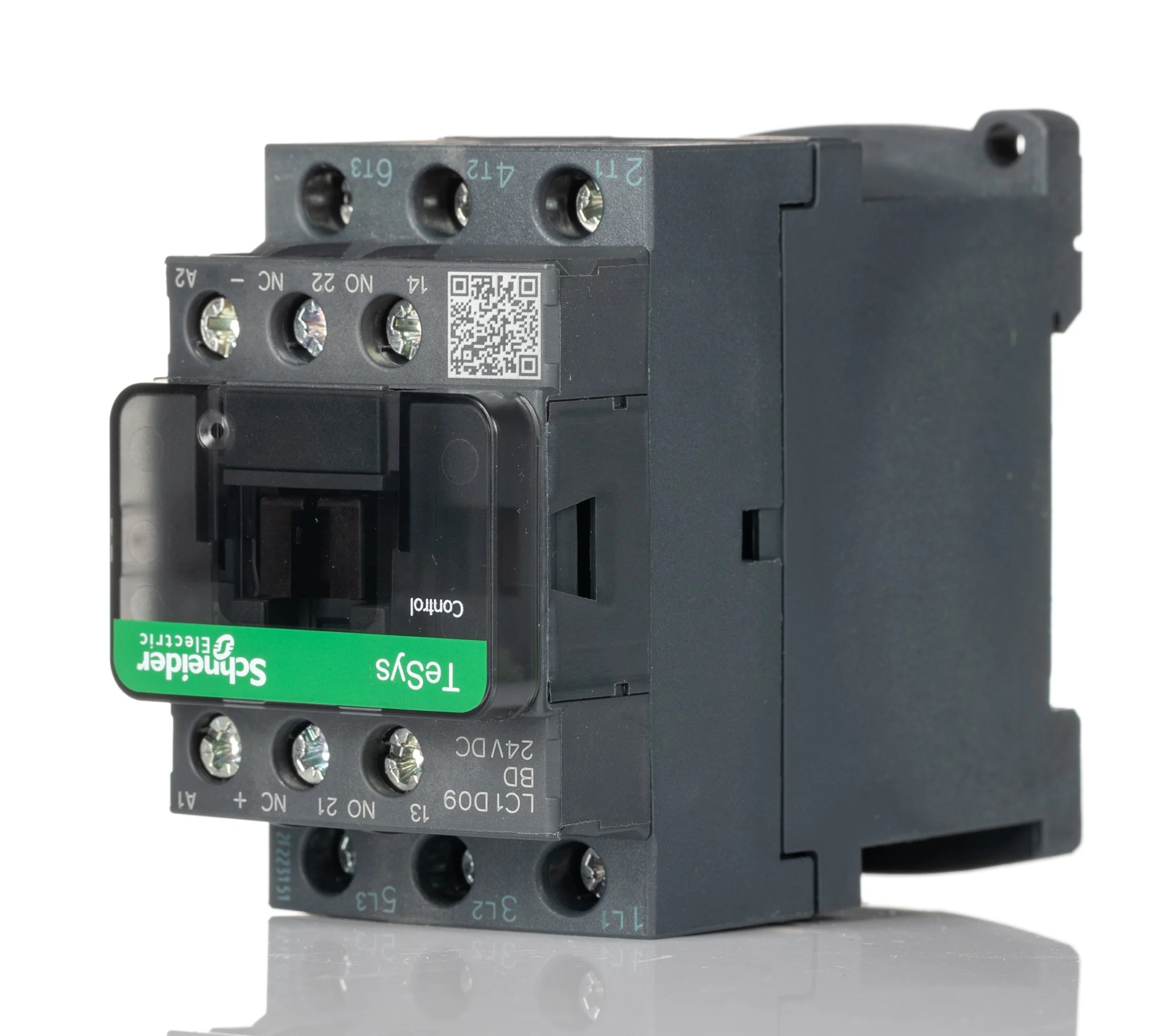
Electrical contractors use contactors to protect installations from overload and short-circuits. Connecting contactors requires knowledge of 3 phase contactor wiring diagrams and AC power. The A1 and A2 terminals in a contactor wiring diagram refer to the primary power-input and output connection points on the contactor’s load side. Learning how to read and interpret contactor wiring diagrams is essential for ensuring proper installation and operation.
Contactor wiring diagrams are diagrams that show how various components of the contactor are connected. Often, these diagrams will include symbols for designating the different types of wires and connections that must be made. They also provide information about which terminals correspond to which components. Understanding contactor wiring diagrams is important for electricians, technicians, engineers, and anyone else who works with them. In this article, we will discuss 3 phase contactor wiring diagrams and their corresponding A1 and A2 terminals.
What Is A3 Phase Contactor?
A 3-phase contactor is an electromechanical device used for controlling large electrical loads. It contains a set of contacts (fixed and movable) that can be opened or closed using a coil. This coil is usually activated by a switch, either on the contactor itself or connected elsewhere in the system. 3-phase contactors are often used in industrial applications, such as electric motors, pumps, compressors, and other equipment. These contactors are usually rated between 4 and 85 amps.
Understanding 3 Phase Contactor Wiring Diagram A1 A2 Terminals
The A1 and A2 terminals in a contactor wiring diagram signify the primary input and output lines for the contactor’s load side. When wiring a contactor, the A1 terminal should receive two traveler wires from the source and the A2 terminal should send two traveler wires to the load.
The traveler wires are the live wires that will be switched on and off by the contactor when the coil is energized or de-energized. Both the A1 and A2 terminals must be correctly wired for the contactor to work correctly. In a 3-phase contactor wiring diagram, the A1 and A2 terminals are always depicted in the same position relative to each other.
Advantages of Installing a 3 Phase Contactor
Installing a 3 phase contactor can have several benefits, including:
- Increased safety: Contactors are designed to reduce the risk of electric shock and fire, making them a much safer option than unprotected wiring.
- Improved reliability: Contactors are designed to withstand high levels of current, making them more reliable in applications with heavy loads.
- Energy savings: By only energizing and de-energizing the electrical load when necessary, contactors can help save energy.
- Ease of maintenance: Contactors are easy to wire and maintain, making them a cost-effective option.
Conclusion
Understanding 3 phase contactor wiring diagrams is essential for electricians and technicians working with contactors. The A1 and A2 terminals signify the primary input and output lines for the contactor’s load side. Installing and maintaining contactors can have numerous advantages, including increased safety, improved reliability, energy savings, and ease of maintenance.

Pdf Wiring Diagram Book Eduardo Cuevas Academia Edu

Electrical Contactor Connection And Wiring 1 Bbe

120v 220v 380v Ac Motor Ford Reverse Wireless Remote Control Switch

Help Wiring Relay D I Y Kit Uk420
25a Power Contactors Silent With Handle

The Beginner S Guide To Wiring A Star Delta Circuit Factomart Singapore

Dol Starter Direct Online Diagram Construction Advantages Electrical4u

What Is Contactor Construction Working Operation Electrical4u

Ac Contactor What Is Self Locking Utmel

Sob Range Two Phase Ssr Celduc Relais

Ac Motor Control Circuits Worksheet Electric
Contactor Help Diynot Forums

Contactor Pole Wiring Question Homebrew Talk Beer Wine Mead Cider Brewing Discussion Forum
A Complete Guide To Contactors Rs Components
Contactor Manual

What Is A Contactor Working Principles Realpars

3 Phase Motor Contactor Wiring Diagram Guide Springer Controls

Reversing Contactor Definition Advantages And Connection Diagrams

Compensating And Definite Time Control Starting Direct Cur Controllers


