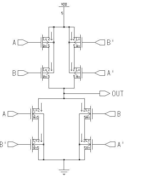
Understanding 3 Input Xor Gate Cmos Circuit Diagram
Finding the right logic gate to implement a given digital system can be a tricky endeavor. While there are many solutions available, some solutions may be better than others depending on the application. One such solution is the three-input exclusive or (XOR) circuit. This type of gate is a key component in modern digital circuits and can provide excellent results if designed and constructed correctly. In this article, we will explore the three-input XOR gate CMOS circuit diagram and how it is used in today's electronics.
What is a 3 Input XOR Gate?
A three-input XOR (exclusive or) gate is a logic gate that outputs a logical one when an odd number of inputs are in the high state. This type of gate is often used in combination with an AND or OR gate to create complex digital circuits. This type of gate is very versatile, as it can be used to facilitate multiple operations such as comparisons, binary addition, and logic functions.
Designing the CMOS Circuit Diagram
The simplest way to construct a three-input XOR gate is to use Complementary Metal-Oxide Semiconductor (CMOS) transistors. To build the transistor, two types of transistors are necessary: an N-channel transistor and a P-channel transistor. The N-channel transistor is used to control the flow of electricity between the input and output terminals. The P-channel transistor is used to shut off the electricity between the input and output.
Interpreting the Diagram
Interpreting the three-input XOR CMOS circuit diagram can be quite daunting at first, but it can be simplified by breaking it down into its individual components. The most basic components of the diagram are the P and N-channel transistors. When the input terminals are both in the high-state, the P-Channel transistor turns on and allows electricity to flow from the input to the output. However, when one of the input terminals is in the low-state, the P-Channel transistor is turned off, thereby preventing electricity from flowing from the input to the output. This results in the output being in the low-state.
Advantages of Using a 3 Input XOR Gate
Using this kind of gate has numerous advantages. Firstly, it has a very fast switching speed, which makes it ideal for use in digital circuits. Additionally, it requires a minimal amount of power to operate, making it extremely efficient and reliable in operation. Finally, it also has a low noise level, which helps to reduce interference and ensure that systems remain functioning correctly.
Conclusion
The three-input XOR gate CMOS circuit diagram provides an excellent example of how the right logic gate combined with the right transistors can form the basis of a powerful digital circuit. This type of gate is versatile, efficient, and reliable in operation, making it an ideal choice for any number of applications. Additionally, understanding the diagram can help engineers to design and build systems that will function optimally.
Lab6 Designing Nand Nor And Xor Gates For Use To Design Full Adders

Basic Cmos Logic Gates Technical Articles
4 Basic Digital Circuits Introduction To

The Improved Circuit Of 3 Input Xor Scientific Diagram

Low Power 3 Input Xor Gate Eeweb

Solved 3 Design A Cmos Circuits To Realize The Following Chegg Com

Q2b Gif
What Is The Output Of A 4 Input Nand Gate When Only 3 Or 2 Inputs Are Applied Quora
Solved 2 15 Consider The Design Of A Cmos 3 Input Xor Chegg Com

Introduction To Xor Gate Projectiot123 Technology Information Website Worldwide

E77 Lab 3 Laying Out Simple Circuits

Dee6113 Practical Work5 Pdf Doent
4 Basic Digital Circuits Introduction To
Design Of Three Input Xor Xnor Using Systematic Cell Methodology

Logic08 Gif

Solved Chapter 1 Problem 8e Solution Cmos Vlsi Design 4th Edition Chegg Com
Lab 6 Emmanuel Sanchez

The Circuit Topology Of New Dscl Gate A 2 Input Xor Xnor Scientific Diagram


