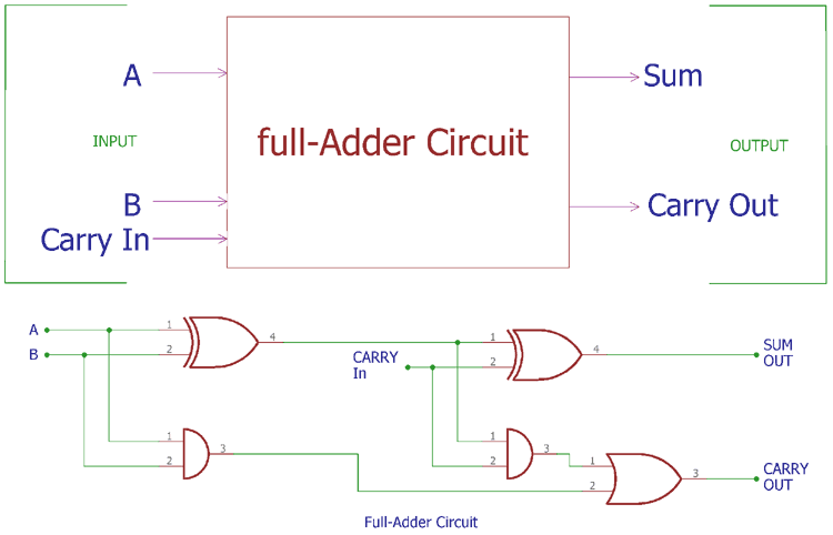
Understanding The Function of 2 Bit Adder Circuit Diagram
2 bit adder circuit diagram is often used by engineers and technicians to demonstrate the basics of digital-logic design. This type of circuit diagram is one of the simplest forms of arithmetic circuits, which are meant to add two binary numbers together in a single cycle. To understand the workings of such a circuit diagram better, it is important to break down its components and the logic behind them.
A 2 bit adder circuit is composed of two separate logic gates, an XOR gate followed by an OR gate. Typically, these two input bits are connected to their respective outputs on the circuit diagram, with the output being the sum of the two inputs and the carry out, or overflow, being the bit that determines whether or not a third bit is needed for addition. This specific type of circuit is one of the easiest to understand and use.
The Components of a 2 Bit Adder
The two main components of a 2 bit adder circuit diagram are the XOR and the OR gates. The XOR gate takes two bits and outputs a 1 if only one of the inputs is a 1 and 0 if both inputs are either 0 or 1. In the 2 bit adder, the XOR gate is used to determine whether an overflow is present. If both inputs are 1, then the result is 1, indicating that an overflow is present as the answer will be greater than 9.
The OR gate, on the other hand, takes two bits and outputs a 0 if both of the inputs are 0 and 1 if at least one of the inputs is 1. In the 2 bit adder, the OR gate is used to determine the sum of the two input bits, with the output remaining 0 if the result is less than 8, and 1 if the result is greater than or equal to 8.
The Logic Behind 2 Bit Adder Circuits
The main logic behind a 2 bit adder is relatively straightforward. Each bit of the two inputs is connected to its respective output, the sum of the two bits, and the overflow bit. If both of the inputs are equal to one, then the output will be 1, indicating an overflow has occurred, as the number can’t be represented by two bits. Otherwise, the sum of the two bits will be equal to the output, while the overflow bit is set to 0.
In this particular type of diagram, the two input bits are connected to two separate logic gates, with their respective outputs each driving the result and the overflow. With this setup, it is easy to calculate the results of the two bits when combined together. For example, if the two input bits are 1 and 0, then the sum of the two bits will be 1, with the overflow bit being 0.
Advantages of 2 Bit Adder Circuits
For those looking to understand basic digital-logic design, the 2 bit adder circuit is a great place to start. It is simple enough to understand without having to learn complex equations and provides a basic insight into how circuits work and the logic behind them. The circuit also allows for fast operation with minimal power consumption, making it ideal for low-power applications such as wearables and embedded systems.
The diagram is also popular among hobbyists as it is easy to construct, as well as being one of the most affordable forms of arithmetic circuits available. This makes it perfect for those looking to experiment with digital-logic design without having to spend too much money.
Conclusion
A 2 bit adder circuit diagram is one of the simpler types of arithmetic circuits available, providing a basic insight into how digital-logic works. They consist of two separate logic gates, an XOR and an OR, which work together to determine the sum of the two inputs as well as if an overflow is present. This type of circuit offers a great introduction to digital-logic for hobbyists and engineers alike, as it is easy to construct and understand without having to learn complex equations.

2 Bit Full Adder A Schematic Of An N Constructed From Scientific Diagram
Design Of 2 Bit Full Adder Circuit Using Double Gate Mosfet

Combinational Circuits

The Truth Table Of 1 Bit Full Adder Scientific Diagram

N Bit Adder

Cs355 Sylabus

1 Bit Full Adder Based On Two Half Adders Scientific Diagram

Adders Subtractors Lesson Objectives Half Adder

Full Adder Circuit Theory Truth Table Construction
2 Bit Alu Circuit Diagram Gadgetronicx

What Is Parallel Binary Adder 2 Bit And 5 Electronics Coach

Lab 3
2 Bit Full Adder Multisim Live

4 Bit Full Adder Using Logic Gates In Proteus The Engineering Projects

2 Bit Full Adder Using Just Thirty Six 555 Timers Hackaday

2 Bit Adder With Full And Half Tinkercad

3 Bit Adder Bvtelectronics Com

Logic Design Adder Circuits In Multisim Steemit
9 Four Bit Adder Mr Bridger S Web Page
